
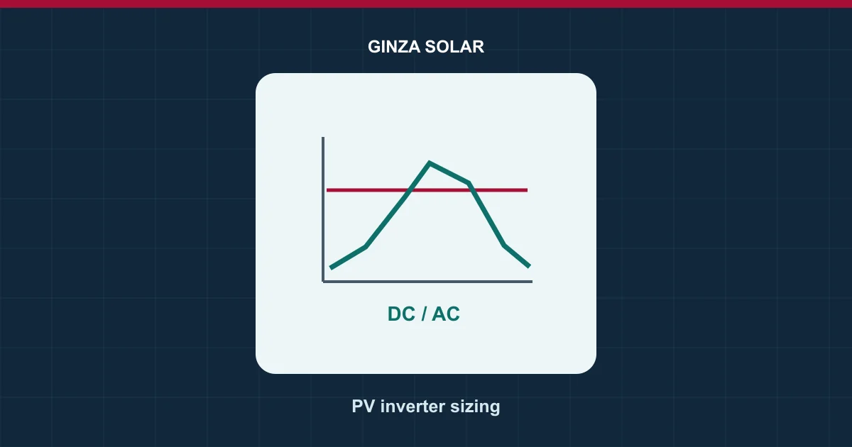
Quick answer. Solar DC/AC ratio divides the array’s rated DC power by the inverter’s rated AC power. A 120 kWp array with a 100 kW AC inverter has a ratio of 1.20. A larger ratio can increase production in lower-irradiance hours while causing more clipping when available solar power exceeds the conversion limit. Choose using annual AC energy and project economics, then verify every electrical and manufacturer limit independently.
This worksheet is for a buyer comparing module counts and inverter options. The examples are fictional and illustrate the questions to ask. A ratio alone cannot establish safe strings, an approved equipment combination or annual output at your site.
What the ratio includes
Use the array’s DC nameplate on a consistent rating basis and the inverter’s stated AC rating. PVsyst’s sizing guidance distinguishes the module rating at standard test conditions from the inverter’s AC output and the DC input needed for that output. Count all connected modules and identify which inverter they feed. A site with several inverters may have different ratios by roof zone or orientation even when the site-wide quotient looks reasonable. Confirm whether the quote uses inverter rated real power, apparent power or a grid export ceiling as its denominator.
For 200 illustrative 600W modules, DC nameplate is 120,000W, or 120 kWp. Dividing by 100 kW AC gives 1.20. If the service connection permits 80 kW export, that limit affects dispatch at the meter. It does not change the hardware ratio of the 120 kWp array and 100 kW inverter. Ask the simulation to separate the two effects.
| Item | Illustrative value | What it answers |
|---|---|---|
| Module array | 200 × 600W = 120 kWp DC | Installed DC nameplate |
| Inverter | 100 kW AC | Named conversion rating |
| DC/AC ratio | 120 ÷ 100 = 1.20 | Array rating relative to inverter rating |
| Utility export limit | 80 kW in this example | Site power-flow constraint, subject to loads and controls |
Clipping is an energy calculation over time
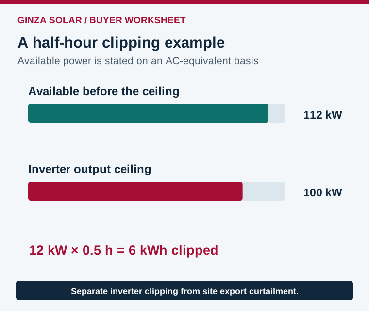
Consider a simulated half-hour with 112 kW of available AC-equivalent PV power before a 100 kW inverter ceiling. The power difference is 12 kW and the interval clipping loss is 12 × 0.5 = 6 kWh. Use the same pre-clipping conversion basis for both values. Subtracting raw DC input watts from an AC output rating without accounting for conversion and conditions gives an inconsistent result.
Now suppose the next half-hour has 96 kW available. That interval has no power-ceiling clipping on the same assumptions. A single noon screenshot cannot reveal the annual loss. Sum the modeled differences over the weather year and inspect the times when clipping occurs. Check whether a flat output trace is due to inverter power, current, temperature, site export control or another operating limit.
Compare additional modules with a larger inverter
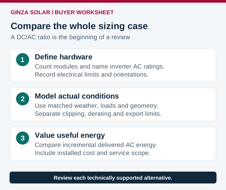
Ask for matched annual cases. Hold weather, layout constraints, orientation, shading, loss assumptions and metering constant while varying the proposed design. Record module count, inverter rating, annual AC production, clipping and export curtailment. If the array area also changes, show that explicitly. A larger inverter can reduce clipping but adds value only when its extra output can be used or exported under the project rules.
Keep different roof orientations visible in the comparison. East- and west-facing groups may peak at different times from a single equator-facing plane. A design with the same total DC rating can therefore produce a different power histogram and clipping loss. Ask the designer to use the actual orientation and tracker allocation. Do not select a ratio from another project’s noon power trace without checking those differences.
Review the metered evidence if an operating site is being expanded. A flat inverter output together with an active power-limit command indicates a different situation from an unconstrained unit at its conversion ceiling. Request the relevant alarms, current, voltage, temperature and export-control signals. The expansion model should reproduce the observed behavior before it predicts the benefit of additional modules or another inverter. When the evidence is incomplete, compare a bounded range and name the missing measurement that would resolve it.
For example, a hypothetical design improvement produces 8 MWh more useful annual energy. At an assumed value of $100 per MWh, the gross annual value is $800. That is a screening calculation. Evaluate the additional installed cost, service costs, financing and the value of energy at the hours it appears before choosing the equipment. An export-limited or low-load site can value additional midday energy differently from an unrestricted site.
Verify voltage and current even if the ratio looks normal
The exact module Voc and temperature coefficient set the cold-voltage check. Hot Vmp, startup behavior and the MPPT window affect operation. Parallel strings and bifacial rear exposure affect current. A permitted array power or a familiar DC/AC ratio does not establish compliance with those limits. Use the string sizing worksheet and record the inverter’s per-tracker and per-input specifications.
Read the manufacturer’s sizing instructions and supported overload conditions. Check site altitude and temperature derating, AC voltage conditions, reactive power obligations and the permitted PV operating range. A nominal 100 kW inverter may have less real-power headroom under certain conditions. Ask for the capability used in the simulation and acceptance test. Where the utility requires reactive support, also review inverter kW and kVA capability.
Include storage and export controls in the model
A compatible DC-coupled battery may accept energy that would otherwise reach an inverter ceiling, but only while the charging path has headroom and the battery can accept energy. State of charge, reserve, battery current and dispatch can restrict recovery. An AC-coupled battery may absorb energy available on the AC bus and reduce site curtailment, while energy already clipped inside the PV inverter is unavailable to it.
Have the model identify which limit created each loss. The AC and DC coupling comparison describes those power paths. Use the export-control checklist if the connection has a restrictive export limit. Confirm that the modeled charging and export commands can be implemented by the proposed controllers.
What a procurement-ready comparison should contain
- Give bidders the location, usable layout, selected module revisions and AC connection requirements.
- Ask for at least two technically supported sizing cases using the same weather and load assumptions.
- Require a loss breakdown that separates clipping, current limitation, thermal derating and export curtailment.
- Request tracker schedules and electrical checks, including the assumptions for bifacial current.
- Compare incremental installed cost against additional useful energy and a documented service plan.
At handover, preserve the array and inverter schedule with the model inputs and released design. If procurement changes module wattage or electrical characteristics, update both the nameplate ratio and the detailed string checks. If the installed inverter firmware or export setting differs from the model, have the design team reconcile the difference before using the estimate as an acceptance baseline.
Frequently asked questions
What DC/AC ratio should every solar project use?
There is no single project-independent choice. Compare supported configurations using site weather, orientation, electrical limits, energy value and connection constraints.
Does clipping mean the inverter is defective?
A designed power limit can cause a normal output plateau. Use the logs and operating conditions to distinguish it from faults, curtailment or derating.
Can a battery eliminate all clipping?
Recovery requires the right power path, charging capacity and dispatch. Model full-battery and unavailable-battery cases as well.
Should I buy more modules or a larger inverter?
Ask for the incremental useful AC energy and full installed-cost change for both options, after checking the supported electrical design.
References and project quotation
- PVsyst inverter and array sizing guidance
- NLR Annual Technology Baseline, PV-plus-battery conversion and clipping context
Compare GINZA PV module options and request a project quotation with the layout, inverter and site operating constraints.