
Quick answer: Solar panel string sizing starts with the exact module and inverter datasheets. Put enough modules in series to keep hot operating voltage inside the inverter’s MPPT range, while keeping cold open-circuit voltage below the strictest applicable voltage limit. Then check how much current each MPPT would see from its parallel strings. Module wattage and the total array kWp do not supply any of those three answers on their own.
This worksheet uses fictional electrical values to show the arithmetic and the questions to resolve with your designer. It is intended for project screening and supplier comparisons. Use the current manufacturer tools, local electrical requirements and site design conditions before releasing a string schedule for construction.
Pull these inputs from the exact revisions being quoted
| Source | Input | Why you need it |
|---|---|---|
| Module datasheet | Voc, Vmp, Isc and Imp at stated rating conditions | Separate open circuit, operating voltage, short circuit and operating current |
| Module datasheet or electrical model | Voc temperature coefficient and a Vmp coefficient or validated model | Estimate cold open-circuit and hot/cold operating voltage |
| Module and equipment ratings | Maximum system voltage, connector rating, series fuse rating | Check applicable limits beyond the inverter’s DC input |
| Inverter input specifications | Absolute maximum DC voltage, operating and full-power MPPT range, startup voltage | Distinguish equipment safety limits from the window for energy production |
| Inverter input map | Per-MPPT and per-input operating current, short-circuit limits and connector assignment | Confirm which physical inputs share a tracker |
| Site and electrical designer | Design temperatures, irradiance, mounting, orientation and bifacial assumptions | Apply the chosen method at the actual site and code basis |
Read units carefully. A coefficient in percent per degree Celsius is divided by 100 for a fractional formula. A coefficient in volts per degree goes directly into an additive voltage calculation. A module’s maximum-power temperature coefficient describes watts and cannot be substituted for its Vmp coefficient. If the latter is missing, request a supported module file or use the manufacturer’s validated calculation method. An online calculator cannot fill in a missing input with confidence.
Worked example: find the cold voltage ceiling
Suppose an illustrative module has Voc = 50.0 V at 25°C and a Voc coefficient of −0.25% per °C. Use a design cold cell temperature of −10°C in this example. Assume 1,000 V is the strictest applicable absolute voltage limit. The manufacturer or local method may require additional factors, tolerances or margin. These sample numbers do not describe any GINZA module.
Cold Voc per module = 50.0 × [1 + (−0.0025) × (−10 − 25)] = 54.375 V. An 18-module string is 978.75 V before extra margin. Nineteen modules give 1,033.13 V, which exceeds the 1,000 V limit and must be rejected. Eighteen is only an arithmetic candidate. If the adopted margin or other component limits make that string too close to the ceiling, shorten it and recheck the lower end of the MPPT window.
Use the design minimum temperature required by the project method, not an annual average. An array can have high open-circuit voltage on a cold morning before the inverter draws operating current. Compare the string to the module maximum system voltage and the ratings of applicable DC equipment as well as to the inverter. Record every limit and the revision that supplied it.
Check the hot and cold MPPT window separately
Now assume Vmp = 41.5 V at 25°C and an illustrative Vmp coefficient of −0.30% per °C. With a hot cell temperature of 70°C, module Vmp is approximately 35.90 V. If the tracker operates from 500 to 850 V, 13 modules would give about 466.67 V and fall below the hot minimum. Fourteen give about 502.57 V and only just pass this screen. At an illustrative cold operating cell temperature of 0°C, Vmp is about 44.61 V per module and an 18-module string is about 803.03 V, below the 850 V upper MPPT limit.
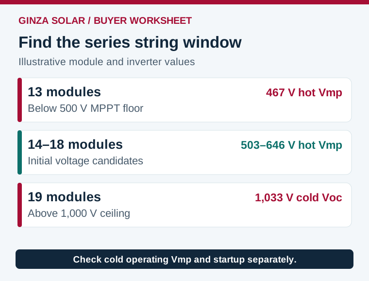
On these assumptions, 14 to 18 modules per string pass the simple voltage calculations. A designer might screen 16 modules first, giving 870.00 V cold Voc and about 574.36 V hot Vmp, before checking tolerances and startup behavior. Separate the absolute DC limit, the MPPT operating range, the range for full rated power and the startup threshold. A 550 V startup threshold, for example, calls for a check of inverter startup conditions and the relevant voltage model. It is not automatically the same test as comparing hot Vmp to a 500 V tracking minimum.
Cell temperature can differ materially from air temperature. A close-mounted roof can run hotter than a ventilated rack in the same weather. Assess operating conditions with a model suitable for the project, and use the prescribed cold-voltage design method. A manual worksheet is a way to catch implausible proposals before detailed simulation.
Check parallel strings against each tracker
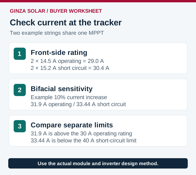
Modules in series raise string voltage. Parallel strings contribute current to the shared tracker. Assume one string has Imp = 14.5 A and Isc = 15.2 A at front-side rating conditions. Two identical strings on the same tracker give 29.0 A operating current and 30.4 A short-circuit current on that basis. If the MPPT ratings are 30 A operating and 40 A short circuit, the simple front-side check passes both.
For a bifacial scenario, assume the model increases both current figures by 10% as a sensitivity test. The same tracker would then see about 31.9 A operating and 33.44 A short circuit before any other factors. The operating limit is now exceeded. Ask the inverter manufacturer how it treats that operating-current case and whether the configuration is supported. An absolute short-circuit limit, operating clipping behavior, and a cable or protection rating are separate constraints. Use the prescribed maximum-current method for the actual module, rear-side irradiance, installation and local requirements. The example’s 10% is not a bifacial design factor.
Two physical DC connectors may share a tracker. Check the wiring map and per-connector rating before splitting strings. Keep dissimilar orientations, module counts and electrical characteristics on separate trackers where the design requires it. If the roof plan needs 96 modules, six strings of 16 may fit the arithmetic. Confirm you can allocate them to suitable trackers and route them around real roof zones, setbacks and shading before treating that as the final layout.
Put the string calculation in the quote package
Send each bidder the site, target DC and AC capacities, exact module and inverter models, design temperatures, row orientations and rear-side assumptions. Request a tracker-by-tracker schedule showing module count per string, number of strings, corrected cold Voc, hot and cold Vmp, maximum operating and short-circuit current, connector mapping, and the limit and margin for each check. Ask who will approve the final design and how a module or inverter substitution will be reviewed.
Record the design case with the BOM. If purchasing switches to another module with the same rated watts but different voltage, current, dimensions, connector or clamping zone, rerun the relevant calculations and update the schedule. For the module count and footprint side of the same job, see the 620W project worksheet. The solar project BOM checklist covers the remaining procurement inputs.
Frequently asked questions
How many panels can I put on one MPPT?
First calculate acceptable modules per series string using cold Voc and hot/cold Vmp. Then check the number of parallel strings against both tracker and individual input current ratings. The answer is model and site specific.
Can I use STC Voc to size a string?
Use STC Voc as an input. Correct it for the applicable cold design condition using the accepted method and compare the result against the strictest system limit with the required margins.
Does a higher-wattage module always need a shorter string?
No. Higher wattage may come from more voltage, more current or both. Compare the model’s electrical values and current revision to the inverter limits.
Do bifacial modules change MPPT sizing?
Rear irradiance can increase current. Use the actual bifacial model and the applicable current calculation, then check the MPPT, input connector, conductors and protection independently.
References and next step
- PVsyst array voltage sizing and inverter constraints
- PVsyst bifacial array modeling and rear-side irradiance
Compare GINZA bifacial solar module options and request the current electrical datasheet for the module revision you want quoted. Include the proposed inverter model and project location.