
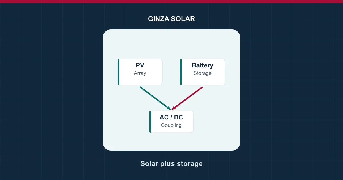
Quick answer. Start an existing solar retrofit by pricing an AC-coupled battery that can share the site’s AC bus with the installed PV inverter. For a new project, compare that layout with a DC-coupled system that can share a DC link and, in many designs, a bidirectional inverter. Choose after comparing the actual power paths, maximum simultaneous output, operating losses and supported outage modes. Coupling type alone does not tell you which offer delivers more usable energy or better backup.
This guide is for a project buyer comparing two quotes for the same site. Put both offers on the same electrical drawing and measure results at the same meter. A single architecture label can cover different equipment boundaries. Have each bidder label its battery interface, controls, point of connection and owner-supplied equipment.
Where the solar and battery paths meet
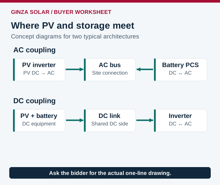
In a typical AC-coupled layout, the PV inverter converts module DC to AC. A separate bidirectional battery power conversion system, or PCS, takes power from the AC bus when charging and returns power to it when discharging. PV and battery can have separate AC ratings. They still share the restrictions of downstream equipment such as the switchboard, transformer, service entrance and utility connection.
In a typical DC-coupled layout, PV and battery connect to a common DC side through the appropriate power electronics. Solar can feed the AC side or charge the battery through a DC path. Battery discharge reaches the AC bus through the shared inverter in this example. The common conversion stage can constrain combined output even when the battery and PV array each have spare capacity. Other DC-coupled designs are possible. Ask for the drawing and ratings of the actual proposed equipment.
Retrofit or new build: make the trade-offs comparable
| Buyer question | AC-coupled starting point | DC-coupled starting point |
|---|---|---|
| Can we retain an installed PV inverter? | Usually the first option to price when existing PV stays on the AC bus | May need changes to the PV inverter, string connections or approved system configuration |
| Where does PV energy go when charging? | Through the PV inverter and then the battery PCS | Through the supported DC charging path before the shared AC stage |
| Can PV and battery discharge together? | Separate converters can contribute, subject to the shared site limit | A shared inverter can limit their combined AC output |
| Can the battery capture otherwise clipped PV? | Energy already clipped inside the PV inverter is generally unavailable on its AC bus | Potentially, if the DC hardware, battery state of charge and dispatch can accept it |
| Will PV work during a grid outage? | Requires an approved grid-forming and PV coordination arrangement | Requires a supported island configuration, startup sequence and load limits |
For a retrofit, document the installed inverter model, firmware, remaining warranty and expansion ports. Ask whether the battery controls can see the existing PV and site meter. Include any switchboard modifications, new metering, outages for installation and utility paperwork in the bid comparison. Retaining PV hardware can reduce electrical rework, while site-level communications and control ownership may still need significant engineering.
For a new build, obtain the usable battery operating range and PV input limits for the proposed inverter, including DC voltage, MPPT current, battery charge/discharge limits and derating. A coordinated design can simplify some interfaces. It can also create dependency on a single converter, approved battery list or firmware pair. Request the service plan and identify which loads or functions remain available when that converter is down.
Worked example: 85 kW of solar with a 30 kW battery request
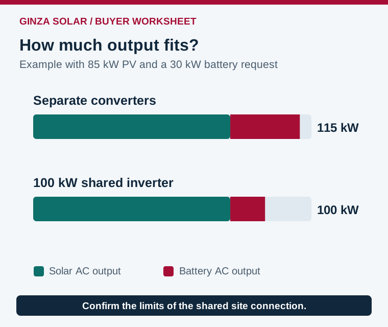
Assume two illustrative bids for a site. One has a 100 kW PV inverter and a separate 50 kW battery PCS. The other has a common 100 kW AC inverter. At the selected instant the PV contributes 85 kW at the AC output. The facility needs 115 kW and requests 30 kW from the battery. Assume ratings are available at site conditions and the connection allows 115 kW of behind-the-meter generation for the AC-coupled case.
The AC-coupled proposal can deliver 85 + 30 = 115 kW in this simplified instant. The DC-coupled proposal with a 100 kW shared inverter has only 15 kW of additional AC headroom at the same solar output. It supplies up to 100 kW through the shared converter and the grid makes up the remaining 15 kW in this grid-connected scenario. If the site connection instead imposed a common 100 kW generation ceiling, the AC-coupled layout would also need control to stay inside that limit. Verify the ceiling at the actual point where the project rule applies.
Now consider a midday interval when the PV DC input could provide more energy than the inverter can export. A compatible DC-coupled layout may redirect some of that energy into the battery. The opportunity depends on available battery charge power, its state of charge, the permitted DC operating range and the site’s dispatch. If the battery is already full or held in reserve, potential clipping recovery can disappear. A model must distinguish PV inverter clipping from curtailment at the point of interconnection. The latter can sometimes be reduced by charging on either side, depending on the controls and topology.
Compare losses and backup on the same boundaries
Ask for an annual model using the same weather, load and tariffs for both bids. Separate PV exported or consumed immediately, PV-to-battery-to-load, grid-to-battery-to-load and energy curtailed. Include overnight standby and HVAC, conversion at partial load, battery power limits, outage reserve and the AC meter boundary. A comparison using one datasheet’s peak converter efficiency misses those differences. Use the AC usable energy and efficiency test guide when agreeing the field measurement.
If resilience matters, specify which circuits must stay live, transfer tolerance, time to restore, battery-only operation and the role of PV or a generator. Ask whether the design can establish an island, restart it after depletion and curtail PV safely when the island load is low. Require a named supported inverter and controller combination. Use the commercial battery backup worksheet for load and reserve assumptions.
For an export limit, define the meter, permitted export and required response with the interconnection reviewer. A site can have AC-coupled storage and export controls, or DC-coupled storage and export controls. The controller must be able to coordinate the installed equipment. See the zero-export solar commissioning guide for the meter and acceptance questions.
What to send for comparable bids
- Supply the existing one-line diagram, utility connection limit, PV string details, inverter firmware and meter locations.
- Share a time series for load and PV, the requested battery service and any reserve or backup requirement.
- Ask each bidder for converter ratings, power-flow limits and simulation results at the same AC boundary.
- List testing responsibility for simultaneous output, export controls, failed communications and island operation where specified.
- Require a breakdown of hardware, interface work, outages, protection, commissioning and support scope.
Frequently asked questions
Which coupling type is best for an existing PV system?
Price an AC-coupled option first if keeping the installed PV inverter is a priority. Compare site controls, switchboard work and backup compatibility against a DC redesign before deciding.
Does DC coupling always recover clipping losses?
Recovery needs a supported charge path, spare battery capacity and suitable dispatch at the clipping interval. Ask for annual recovery modeled from site data.
Do separate inverters guarantee their ratings add at the grid meter?
Check the common electrical equipment, utility limit and control strategy. Two converter ratings can exceed what the connection permits.
Can both architectures support backup?
Both can be designed for backup with approved equipment and controls. Confirm grid forming, isolation, transfer and available output in the actual proposed configuration.
References and project quotation
- National Laboratory of the Rockies research on PV and battery configuration and dispatch
- Annual Technology Baseline, PV-plus-battery architectures
Compare GINZA commercial energy storage options and request an architecture review with your one-line drawing, current PV and the required duty cycle.