
Quick Answer
Solar power system commissioning is the final technical verification process before a PV system is connected, handed over, and accepted for operation. For EPC contractors, installers, and project owners, commissioning is not just a formality. It confirms that the system is safe, compliant, correctly configured, and capable of producing the expected energy output.
Many solar project issues appear after installation because commissioning was rushed: reversed string polarity, incorrect inverter parameters, loose DC connectors, insulation faults, wrong CT ratio settings, unverified BMS communication, or incomplete handover documents. A strong commissioning process prevents these problems before the system enters commercial operation.
A complete solar commissioning checklist should cover document review, visual inspection, DC and AC electrical tests, inverter configuration, battery and BMS checks, monitoring setup, performance verification, and final handover documentation. For EPC projects, the goal is to prove safety, compliance, performance, and handover readiness before commercial operation.
Who This Guide Is For
This guide is written for EPC contractors, solar installers, project owners, O&M teams, and procurement teams preparing PV, hybrid solar, or solar-plus-storage projects for acceptance. It is most useful when the buyer needs a practical commissioning procedure, not only a standards reference.
GINZA Tech Solar is a Chinese solar battery and PV material manufacturer based in Shenzhen, supporting EPC contractors, installers, and wholesale buyers with LiFePO4 batteries, commercial ESS cabinets, solar panels, solar mounting systems, and turnkey solar project solutions for international markets.

—
1. What Is Solar Power System Commissioning?
Solar power system commissioning is the structured process of verifying a newly installed PV system before commercial operation. It includes safety inspection, electrical testing, inverter and protection setup, monitoring activation, performance validation, and project handover documentation.
Commissioning usually happens after mechanical installation and electrical wiring are complete, but before the system is formally handed over to the owner or connected for normal operation. For grid-connected systems, the process must also align with local utility interconnection requirements.
Commissioning vs. Installation vs. O&M
| Stage | Main Objective | Typical Owner | Output |
|---|---|---|---|
| Installation | Build the physical system | EPC / installer | Installed PV array, inverter, wiring, battery, protection devices |
| Commissioning | Verify safety, configuration, and performance | EPC / commissioning engineer | Test reports, configuration records, acceptance certificate |
| Operation & Maintenance | Keep the system safe and productive | O&M team / owner | Maintenance logs, performance reports, corrective actions |
Why Commissioning Matters for B2B Projects
For small residential projects, commissioning may be a short inspection and inverter setup process. For commercial, industrial, hybrid, and ESS projects, commissioning becomes much more important because the cost of mistakes is higher.
A 500 kW rooftop system with one incorrectly configured inverter may lose thousands of kWh before the issue is noticed. A commercial ESS project with incorrect BMS-inverter communication may fail to charge, trip under load, or refuse to enter backup mode. A utility-interconnected system with incorrect protection settings may fail approval from the grid operator.
Commissioning protects four things:
- Safety — confirms insulation, grounding, polarity, protection devices, and emergency shutdown behavior.
- Performance — verifies that PV strings, inverters, batteries, and monitoring systems operate as expected.
- Compliance — supports inspection, utility approval, warranty activation, and customer handover.
- Commercial acceptance — provides evidence for milestone payment, project closeout, and O&M transfer.
Soft CTA: Planning a commercial PV or solar-plus-storage project? Send GINZA Tech Solar your project BOM for component review before procurement and commissioning.
—
2. Solar Commissioning Standards and Compliance References
IEC 62446-1 is the most important international reference for grid-connected PV system commissioning because it covers customer handover documentation, commissioning tests, inspection criteria, and verification of safe installation and correct operation. Regional projects may also require NEC, UL, IEEE, AS/NZS, or local utility standards.
Commissioning standards do not replace local electrical codes. Instead, they give EPC contractors a structure for what must be inspected, tested, recorded, and delivered.
Key Standards for Solar Power System Commissioning
| Standard / Code | Region / Use | Commissioning Relevance |
|---|---|---|
| IEC 62446-1 | International | Documentation, commissioning tests, inspection criteria, customer handover for grid-connected PV systems |
| IEC 62446-2 | International | Preventive, corrective, and performance-related maintenance requirements for grid-connected PV systems |
| IEC 62548 | International | PV array design and safety requirements, including DC array wiring and protection provisions |
| IEC 61215 | International | Design qualification of terrestrial PV modules for long-term outdoor operation |
| IEC 61730 | International | PV module safety qualification, including construction and safety testing |
| IEC 62116 | International | Test procedure for anti-islanding protection of utility-interconnected PV inverters |
| IEEE 1547 | North America / DER interconnection | Interconnection and interoperability requirements for distributed energy resources |
| UL 1741 | North America | Safety standard for inverters, converters, controllers, and DER interconnection equipment |
| NEC Article 690 / NFPA 70 | United States | Electrical code requirements for PV systems |
| AS/NZS 5033 | Australia / New Zealand | Installation and safety requirements for PV arrays |
What IEC 62446-1 Means in Practice
IEC 62446-1 is useful because it separates commissioning into three practical areas:
- System documentation — drawings, datasheets, layout, labels, operating manuals, and handover records.
- Inspection — visual and mechanical checks before energization.
- Testing — electrical measurements and functional verification to confirm safe operation.
For international EPC projects, IEC 62446-1 should be treated as a commissioning documentation framework. The actual test values and acceptance criteria must still follow the approved design, local electrical codes, utility interconnection requirements, and equipment manuals.
Compliance Warning
Only qualified electrical professionals should perform commissioning tests. DC insulation resistance testing, open-circuit voltage testing, high-voltage battery commissioning, and grid-interconnection checks can expose workers to dangerous voltages. Always follow local lockout/tagout, PPE, and electrical safety procedures.
—
3. Pre-Commissioning Checklist Before Energization
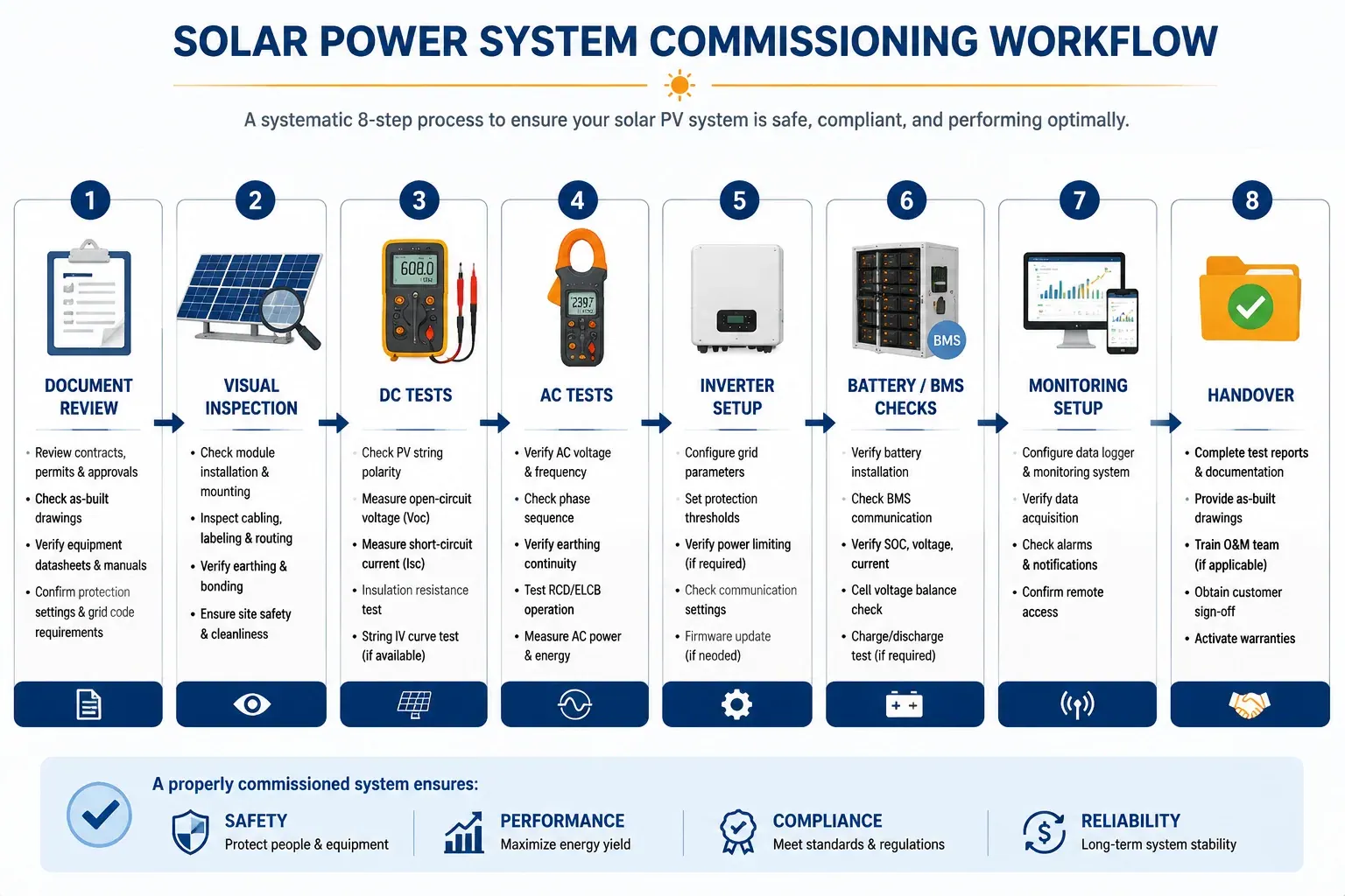
Pre-commissioning confirms that the system is physically complete, correctly labeled, mechanically secure, and safe to test. No inverter, battery, or PV string should be energized until visual inspection, documentation review, and safety checks are complete.
This stage often catches the most avoidable problems: missing labels, wrong cable routes, loose connectors, poor torque, incomplete grounding, unsealed roof penetrations, incorrect string grouping, and mismatch between the as-built installation and the design drawings.
Pre-Commissioning Document Review
Before going to site, prepare and check the following documents:
| Document | Purpose | Required Before Testing? |
|---|---|---|
| Approved single-line diagram | Confirms electrical topology and protection devices | Yes |
| As-built drawings | Confirms actual installation matches final site condition | Yes |
| PV module datasheets | Confirms Voc, Isc, current rating, temperature coefficients | Yes |
| Inverter datasheets and manuals | Confirms DC input limits, AC settings, commissioning steps | Yes |
| Battery / ESS manuals | Confirms voltage window, BMS protocol, pre-charge and safety steps | Yes, for hybrid/ESS |
| String schedule | Confirms module count per string and MPPT assignment | Yes |
| Cable schedule | Confirms cable type, size, polarity, and routing | Yes |
| Protection device schedule | Confirms fuse, breaker, SPD, isolator, and RCD/RCMU ratings | Yes |
| Test equipment calibration records | Confirms measurements are valid | Yes |
| Utility approval / grid connection permit | Confirms permission to energize grid-connected equipment | Site dependent |
Visual Inspection Checklist
| Inspection Item | What to Check | Common Failure |
|---|---|---|
| PV module condition | No broken glass, hot spots, backsheet damage, frame deformation | Transport damage not recorded |
| Mounting system | Correct clamps, torque, grounding washers, rail alignment | Loose clamps or missing mid-clamps |
| Cable routing | UV-resistant routing, no sharp edges, no water traps | Cables touching roof surface or metal edges |
| DC connectors | Same connector type, fully seated, correct polarity | Mixed connector brands or loose MC4 connectors |
| String labels | String ID matches drawings and combiner box | Wrong string order |
| DC isolators | Correct rating and accessible location | Underrated isolator or wrong enclosure IP rating |
| Grounding / bonding | Continuity across rails, modules, frames, and equipment | Missing bonding jumper |
| AC distribution | Breakers, meters, CTs, and protection devices match design | CT installed backwards |
| Inverter location | Clearance, ventilation, IP rating, shade, access | Insufficient heat dissipation clearance |
| Battery / ESS cabinet | Level base, ventilation, emergency stop, clear access | Cabinet too close to wall or heat source |
| Fire safety | Warning labels, shutdown instructions, fire access path | Missing emergency labels |
Safety Controls Before Testing
Before energizing any circuit:
- Confirm that all team members understand the test sequence.
- Establish lockout/tagout control.
- Verify suitable PPE for DC and AC measurements.
- Confirm that fire extinguishers and emergency isolation points are accessible.
- Check that weather conditions are safe for roof work and outdoor electrical testing.
- Confirm that test equipment voltage ratings exceed the expected system voltage.
- Record site conditions such as irradiance, temperature, and weather.
Soft CTA: Need component-level review before commissioning? Use our solar project BOM checklist to verify that panels, inverters, batteries, breakers, cables, and protection devices match the final design.
—
4. Electrical Commissioning Tests for Solar PV Systems
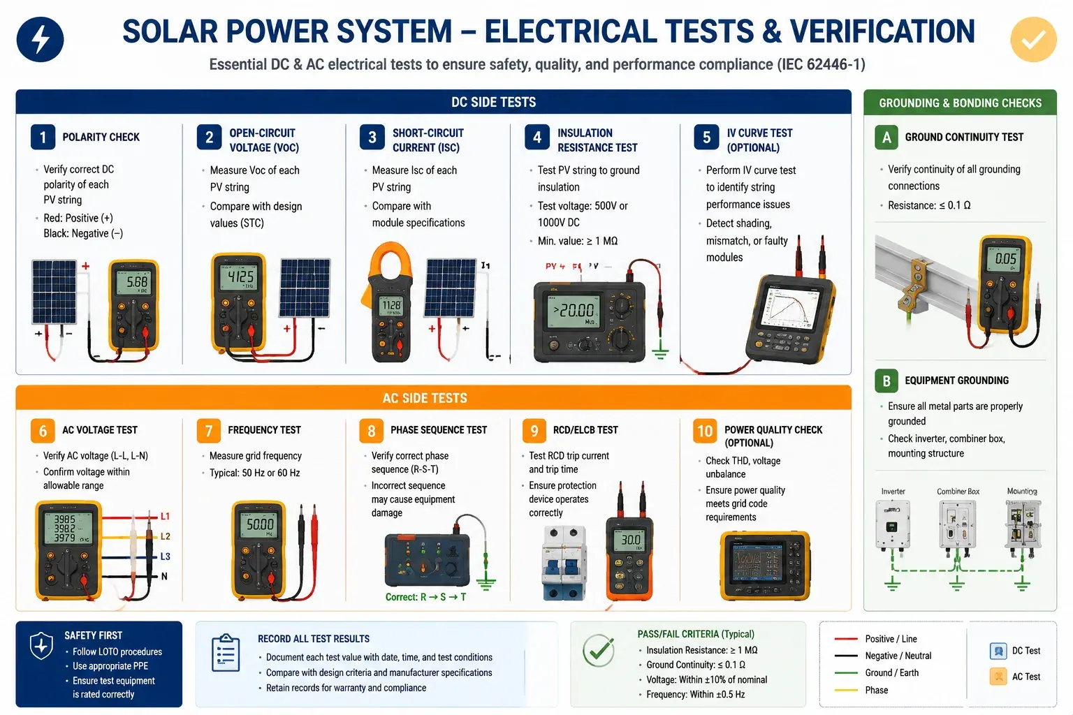
Core solar commissioning tests include string polarity, open-circuit voltage, short-circuit current or operating current, insulation resistance, grounding continuity, AC voltage, protection device verification, and inverter startup checks. These tests confirm that the PV system is wired correctly and safe to energize.
Electrical testing must follow the approved commissioning method statement and local safety procedures. Never disconnect live DC connectors under load unless the connector and procedure are designed for that operation.
Essential DC-Side Tests
| Test | Purpose | Typical Acceptance Logic |
|---|---|---|
| String polarity test | Confirms positive and negative conductors are not reversed | Polarity must match drawings and inverter input |
| Open-circuit voltage (Voc) | Confirms string length and module wiring | Measured Voc should align with expected value adjusted for temperature |
| String current test | Confirms string continuity and module output consistency | Similar strings under similar irradiance should show comparable current |
| Insulation resistance test | Detects ground faults or insulation damage | Must meet local code, equipment manual, and project specification |
| Ground continuity test | Confirms bonding path for metallic components | Low-resistance continuity across grounding path |
| Combiner box inspection | Verifies fuse ratings, SPD status, terminals, labels | All components match design and are properly secured |
Essential AC-Side Tests
| Test | Purpose | Typical Acceptance Logic |
|---|---|---|
| Grid voltage measurement | Confirms phase voltage and frequency are within inverter range | Must match inverter and utility requirements |
| Phase sequence test | Confirms correct phase rotation for three-phase systems | Must match inverter and site distribution |
| Breaker and isolator check | Confirms protection device rating and operation | Correct rating, mechanical operation, labeling |
| Grounding and neutral verification | Confirms safe AC connection | Must comply with local electrical code |
| CT / meter verification | Confirms power meter direction and ratio | Import/export direction and CT ratio must be correct |
| Protection relay test | Confirms relay settings if external relay is used | Must match approved grid protection study |
Expected Voc Calculation Example
Before testing, calculate expected string voltage so field measurements can be interpreted correctly.
Example: A PV string has 20 modules. Each module has a rated Voc of 49.5 V at STC. The measured module temperature is lower than STC, causing Voc to rise.
- STC string Voc = 20 × 49.5 V = 990 V
- If cold-temperature correction increases voltage by 8%, expected Voc ≈ 990 × 1.08 = 1,069 V
- If measured Voc is around 1,060–1,080 V, the string is likely wired correctly.
- If measured Voc is around 530 V, the string may have only half the expected modules connected.
- If measured voltage is negative, polarity is reversed.
This calculation is especially important for high-voltage string inverters where exceeding the maximum DC input voltage can damage equipment or void warranty.
Common Electrical Test Failures
| Symptom | Likely Cause | Corrective Action |
|---|---|---|
| Negative DC voltage | Reversed polarity | Trace string, correct conductor labeling and connection |
| Voc lower than expected | Missing modules, disconnected connector, wrong string length | Inspect string map and connectors |
| One string current much lower than others | Shading, damaged module, high-resistance connector | Compare irradiance, inspect modules, perform IV curve test if needed |
| Insulation resistance fails | Damaged cable, water ingress, pinched conductor | Isolate sections and locate fault |
| Inverter trips at startup | Grid voltage/frequency issue, wrong country code, incorrect AC wiring | Verify AC settings and utility requirements |
| Export power reads negative | CT direction reversed | Correct CT orientation and meter configuration |
—
5. Inverter Commissioning Procedure
Inverter commissioning verifies that the inverter is electrically safe, configured for the correct grid code, assigned to the right MPPT inputs, communicating with monitoring systems, and operating within design limits. Incorrect inverter settings are one of the most common causes of failed solar project handover.
The inverter is the control center of a grid-connected PV system. In hybrid systems, it also coordinates battery charging, backup output, generator input, export limitation, and energy management logic.
Step-by-Step Inverter Commissioning Checklist
| Step | Action | Verification |
|---|---|---|
| 1 | Confirm model and serial number | Matches approved equipment list |
| 2 | Check DC input assignment | Strings connected to correct MPPTs |
| 3 | Check AC connection | Correct phase, voltage, breaker, grounding |
| 4 | Select country / grid code | Matches approved utility requirement |
| 5 | Configure power limits | Export limit, active power limit, reactive power setting |
| 6 | Configure protection settings | Voltage/frequency ride-through, anti-islanding, relay settings |
| 7 | Set date, time, and timezone | Monitoring data timestamps are correct |
| 8 | Connect monitoring | Wi-Fi, Ethernet, RS485, 4G, or data logger online |
| 9 | Confirm firmware version | Matches project specification or approved version |
| 10 | Start inverter | Verify normal operation and no active alarms |
| 11 | Record operating data | DC voltage/current, AC power, grid voltage/frequency |
| 12 | Save configuration backup | Export settings or take screenshots for handover |
Inverter Parameters to Record
At handover, record these parameters:
- Inverter brand, model, serial number
- Firmware version
- Country code / grid code
- MPPT voltage and current per input
- AC output voltage, current, frequency, and power
- Power factor setting
- Export limitation setting
- Communication protocol and monitoring account
- Alarm history at commissioning
- Any modified protection settings
- Utility witness-test result, if required
For hybrid projects, inverter commissioning must also include battery communication verification. See our inverter-battery communication verification guide and high voltage ESS options before pairing LiFePO4 batteries with hybrid inverters.
Inverter Commissioning Mistakes to Avoid
- Using the wrong grid code — may cause nuisance trips or utility rejection.
- Ignoring firmware compatibility — can break battery communication or monitoring.
- Mixing string lengths on one MPPT — reduces yield and causes current mismatch.
- Skipping CT verification — can cause export limitation or self-consumption logic to work backwards.
- Not saving screenshots — makes future troubleshooting harder.
- Leaving default passwords unchanged — creates cybersecurity and O&M access risks.
—
6. Battery and ESS Commissioning for Hybrid Solar Systems
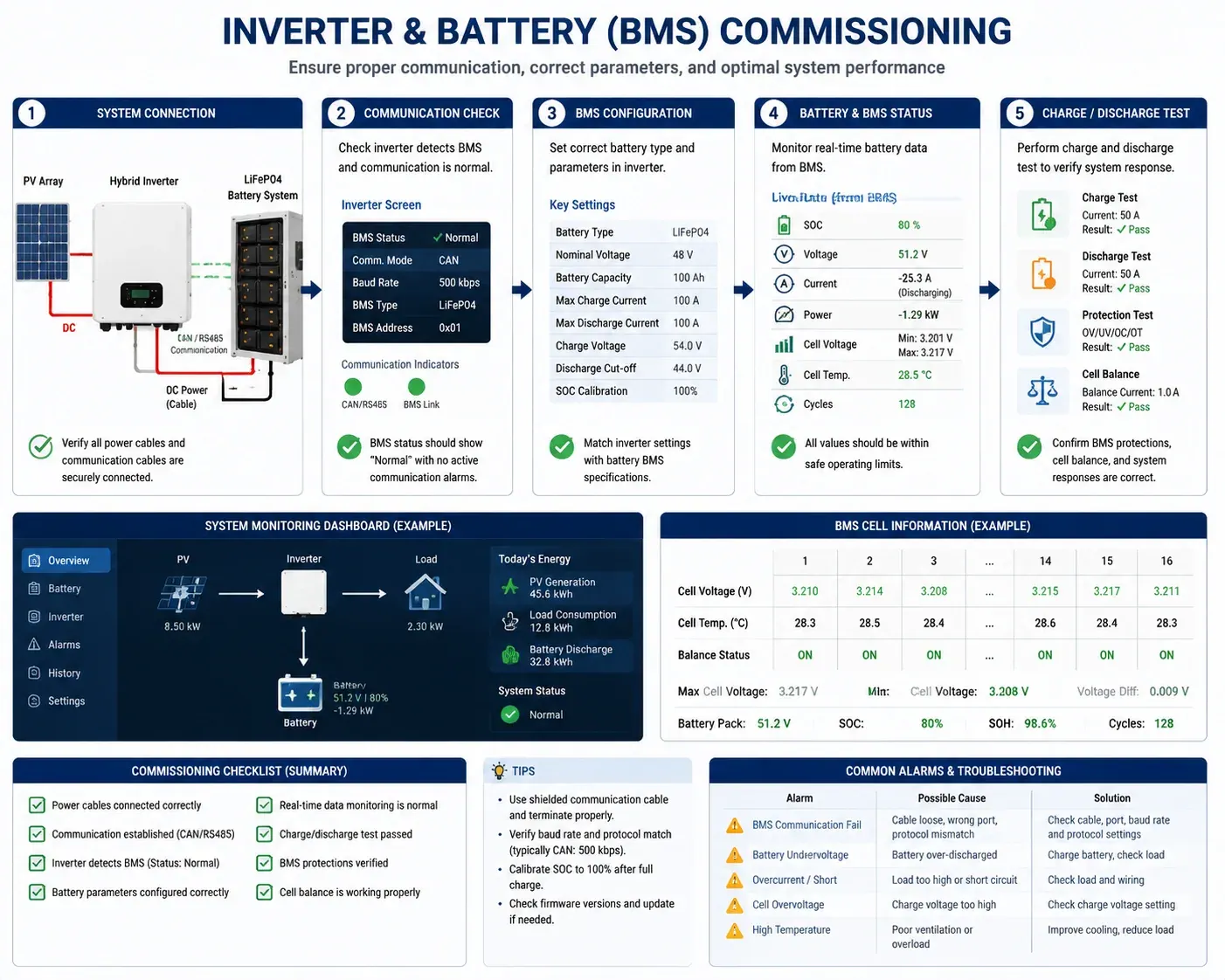
Battery commissioning verifies that the battery system is electrically safe, correctly addressed, properly communicating with the inverter or EMS, and operating within the approved voltage, current, temperature, and state-of-charge limits. For LiFePO4 systems, BMS communication is the most important commissioning item.
A solar-plus-storage project has more commissioning risk than a PV-only project. The battery is not only an energy storage device; it is a controlled system with protection logic, communication protocols, firmware, current limits, SOC estimation, and safety interlocks.
Battery Commissioning Checklist
| Item | What to Verify | Why It Matters |
|---|---|---|
| Battery model and capacity | Matches approved BOM and quotation | Prevents wrong capacity handover |
| Module serial numbers | Recorded for warranty and traceability | Required for future service |
| Battery voltage | Within allowed startup range | Prevents inverter startup fault |
| Polarity | Correct DC polarity before connection | Prevents equipment damage |
| Grounding | Cabinet and rack grounding complete | Ensures electrical safety |
| BMS status | No active protection fault | Confirms battery is ready |
| DIP switch / address | Correct address for parallel modules | Prevents communication conflict |
| Communication cable | CAN / RS485 wiring correct | Enables inverter-BMS data exchange |
| Protocol selection | Correct inverter protocol selected | Prevents SOC and current limit errors |
| Firmware version | Approved or compatible version | Reduces communication failures |
| Charge/discharge current limit | Matches inverter and battery spec | Prevents overcurrent trips |
| Temperature sensors | Readings normal | Prevents unsafe operation |
| Emergency stop | Functional test completed | Confirms safety response |
| SOC calibration | Initial SOC reasonable and recorded | Supports accurate operation |
| Parallel operation | Current sharing verified | Prevents unequal module loading |
LiFePO4 Battery Commissioning Notes
LiFePO4 batteries are widely used in solar energy storage because they offer stable chemistry, long cycle life, and good safety performance. But commissioning still requires careful checks.
For rack-mounted and high-voltage LiFePO4 systems:
- Do not connect battery modules with large voltage differences.
- Confirm module address settings before parallel communication.
- Use the battery manufacturer's recommended CAN or RS485 protocol.
- Verify the inverter displays battery voltage, SOC, allowable charge current, and allowable discharge current.
- Check whether the BMS allows charging and discharging after startup.
- Confirm the battery breaker, fuse, and DC isolator ratings.
- Test backup mode only after normal grid-connected operation is stable.
- Record fault codes and screenshots during first startup.
For deeper product selection guidance, see our LiFePO4 battery selection guide and high voltage battery safety guide.
ESS Functional Tests
| Test | Purpose | Expected Result |
|---|---|---|
| Charge test | Confirms inverter can charge battery | Battery current and SOC increase normally |
| Discharge test | Confirms battery can supply load | Battery current flows to inverter/load |
| Backup mode test | Confirms critical load output works | Critical loads remain powered during simulated outage |
| Grid recovery test | Confirms return from backup to grid mode | System reconnects without fault |
| EMS schedule test | Confirms time-of-use control | Battery follows charge/discharge schedule |
| Export limitation test | Confirms no unwanted grid export | Meter and inverter limit export correctly |
| Emergency stop test | Confirms safety shutdown | System isolates as designed |
Common Battery Commissioning Failures
| Failure | Likely Cause | Solution |
|---|---|---|
| Inverter cannot detect battery | Wrong protocol, cable pinout, address, or firmware | Verify protocol, cable, address, firmware |
| SOC stays at 0% or 100% | BMS data not mapped correctly | Check inverter battery profile |
| Battery trips during discharge | Current limit too low or battery imbalance | Check current settings and module voltage |
| Parallel batteries show unequal current | Different SOC or internal resistance | Balance modules and verify wiring |
| Battery does not charge from PV | EMS mode, grid code, or charge window issue | Check operating mode and schedule |
| Backup output fails | EPS wiring or transfer logic incorrect | Test backup circuit and inverter settings |
—
7. Performance Verification and Monitoring Setup
Performance verification confirms that the commissioned solar system is producing energy consistent with irradiance, temperature, system design, and equipment ratings. Monitoring setup ensures that underperformance, alarms, and communication failures can be detected after handover.
Commissioning is not complete when the inverter turns on. A system can start successfully and still underperform due to string mismatch, shading, wrong CT settings, clipped output, communication errors, or incorrect monitoring configuration.
Minimum Performance Data to Record
Where the handover includes infrared inspection, add the inspection method, operating conditions, asset identifiers and original image files to the evidence register. Use the PV thermal survey guide to define comparable conditions and assign follow-up.
| Data Point | Why It Matters |
|---|---|
| Irradiance at time of test | Needed to interpret PV output |
| Module temperature | Affects voltage and power |
| DC voltage and current per MPPT | Confirms string behavior |
| AC voltage, current, frequency, and power | Confirms grid-side operation |
| Daily energy generation | Establishes first-day output baseline |
| Inverter efficiency / power curve | Identifies abnormal conversion losses |
| Battery charge/discharge power | Confirms ESS behavior |
| SOC trend | Confirms battery monitoring |
| Alarm log | Confirms system is fault-free at handover |
| Monitoring portal status | Confirms remote access for O&M |
Performance Ratio Quick Check
For commercial projects, performance ratio (PR) is often used to compare actual output with expected output under measured irradiance. During commissioning, a simplified check can help identify obvious problems.
Simplified PR concept:
Performance Ratio = Actual AC Energy Output ÷ Expected Energy Output Under Measured IrradianceA full PR calculation should use accurate irradiance sensors, temperature correction, system losses, and modeling assumptions. During commissioning, use PR as a screening tool, not a final bankability result.
Monitoring Setup Checklist
| Monitoring Item | Checkpoint |
|---|---|
| Data logger online | Confirm Ethernet / Wi-Fi / 4G signal |
| Inverter visible in portal | Device serial number appears correctly |
| Battery visible in portal | SOC, voltage, current, alarms visible |
| Meter visible in portal | Import/export values correct |
| CT direction correct | Load and export data make sense |
| Alert rules configured | Alarms sent to responsible O&M contact |
| Customer account created | Owner has appropriate access |
| EPC account access retained | EPC can support warranty and troubleshooting |
| Timezone correct | Daily production data aligns with local time |
| Data export available | Reports can be downloaded for O&M |
Monitoring Handover Tip
Do not use a personal installer email as the only admin account. Create project-level access, then assign permissions to the owner, EPC, O&M provider, and manufacturer support team if needed.
—
8. Documentation and Handover Package
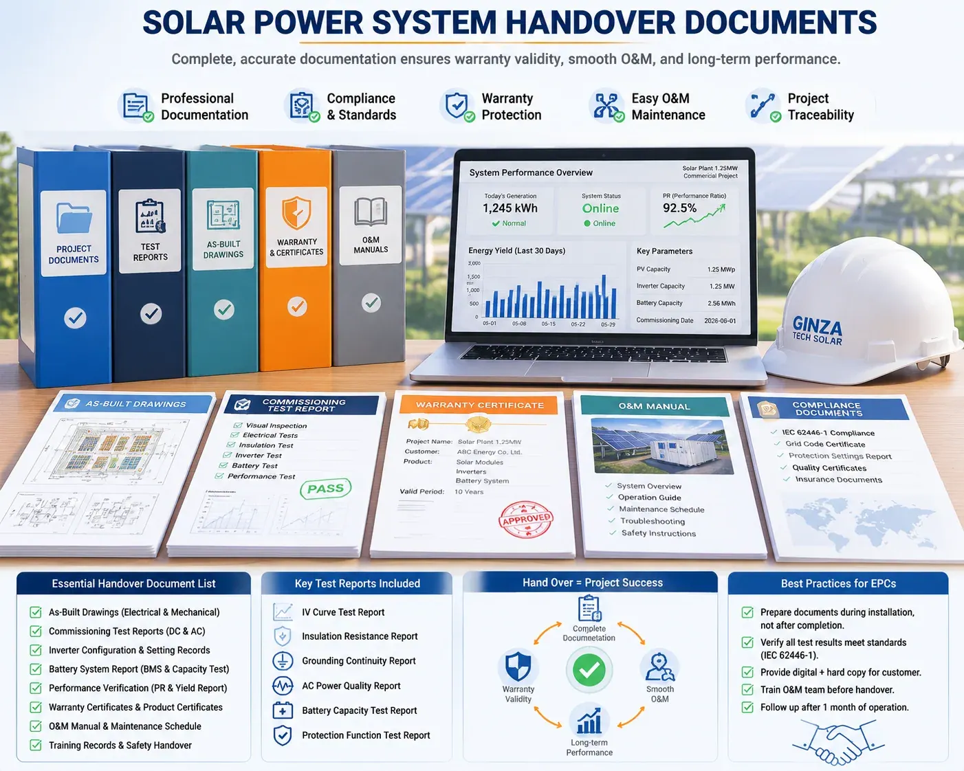
A complete solar commissioning handover package should include as-built drawings, electrical test records, inverter and battery configuration records, equipment datasheets, warranty documents, monitoring access, safety labels, O&M instructions, and a signed commissioning certificate.
Good handover documentation protects both the project owner and the EPC. It reduces disputes, accelerates warranty claims, supports insurance review, and gives the O&M team the information needed to operate the system safely.
Recommended Handover Document List
| Document | Required for PV-Only | Required for Hybrid / ESS |
|---|---|---|
| As-built single-line diagram | Yes | Yes |
| PV array layout | Yes | Yes |
| String schedule | Yes | Yes |
| Cable schedule | Yes | Yes |
| Protection device schedule | Yes | Yes |
| Grounding / bonding record | Yes | Yes |
| DC test records | Yes | Yes |
| AC test records | Yes | Yes |
| Insulation resistance test report | Yes | Yes |
| Inverter configuration report | Yes | Yes |
| Monitoring login details | Yes | Yes |
| Warranty certificates | Yes | Yes |
| O&M manual | Yes | Yes |
| Battery serial number list | No | Yes |
| BMS configuration record | No | Yes |
| Battery startup report | No | Yes |
| ESS emergency shutdown instructions | No | Yes |
| Backup load test report | No | If backup is included |
| EMS schedule configuration | No | If EMS is included |
Commissioning Certificate Template
A simple commissioning certificate should include:
- Project name and location
- Client / owner name
- EPC / installer name
- Commissioning date
- System size in kW and kWh, if ESS is included
- PV module brand, model, quantity
- Inverter brand, model, quantity
- Battery brand, model, quantity
- Test standards and local codes referenced
- Summary of inspection results
- Summary of electrical test results
- List of unresolved punch-list items, if any
- Signature of commissioning engineer
- Signature of client or owner's representative
Warranty Activation Checklist
Many manufacturers require specific documents before warranty support is accepted:
- Product serial numbers
- Installation date
- Commissioning date
- Photos of installation
- Inverter and battery screenshots
- System operating parameters
- Proof that the system was installed according to manual requirements
- Monitoring portal registration
For international projects, keep these records in English and the local language when possible.
—
9. Common Solar Commissioning Failures and Troubleshooting
The most common solar commissioning failures are reversed polarity, low insulation resistance, wrong inverter grid code, CT direction errors, failed monitoring setup, battery communication faults, and missing handover documents. A structured checklist helps EPC teams identify and correct these issues before customer acceptance.
Commissioning should always produce a punch list. The goal is not to pretend the installation is perfect; the goal is to identify all defects, classify risk, assign responsibility, and close issues before final handover.
Troubleshooting Matrix
| Problem | Likely Cause | Priority | Recommended Action |
|---|---|---|---|
| Inverter does not start | No grid voltage, DC voltage too low, DC isolator off | High | Verify AC supply, DC voltage, isolator position |
| Inverter shows insulation fault | Damaged cable, water ingress, connector issue | Critical | Do not energize; isolate strings and test sections |
| Inverter shows grid fault | Wrong grid code, voltage/frequency out of range | High | Check AC measurements and utility requirements |
| PV output lower than expected | Shading, string mismatch, soiling, wrong MPPT grouping | Medium | Compare string currents and inspect layout |
| Export limiter not working | CT reversed, wrong meter setting, communication failure | High | Verify CT direction and meter mapping |
| Monitoring offline | Network issue, wrong logger setup, SIM not active | Medium | Test network and reconnect data logger |
| Battery not detected | Wrong CAN/RS485 cable, protocol mismatch, address conflict | High | Check communication wiring and protocol |
| Battery trips during startup | Voltage mismatch, BMS protection, incorrect current limit | High | Check module voltage, SOC, and current settings |
| Backup load not powered | EPS circuit wiring error or backup mode disabled | High | Verify backup circuit and inverter settings |
| Customer refuses handover | Missing documentation or unresolved punch list | Medium | Complete handover pack and sign acceptance form |
Punch-List Classification
Use a simple priority system:
| Level | Meaning | Example | Handover Allowed? |
|---|---|---|---|
| Critical | Safety or compliance risk | Insulation failure, exposed conductor, fire safety issue | No |
| High | System cannot operate correctly | Inverter fault, battery communication failure | Usually no |
| Medium | System works but needs correction | Monitoring offline, label missing | Conditional |
| Low | Cosmetic or documentation improvement | Minor cable dressing, photo update | Yes, with closeout date |
Root Cause Documentation
For each fault, record:
- Date and time
- Equipment involved
- Alarm code or measurement
- Photo or screenshot
- Root cause
- Corrective action
- Person responsible
- Retest result
- Closeout date
This makes future O&M work much easier and helps protect the EPC if a customer later claims that the system was never commissioned correctly.
—
10. Regional Commissioning Requirements: IEC, UL, NEC, and Utility Rules
Solar commissioning requirements vary by country. IEC 62446-1 provides a strong international framework, while North American projects typically require compliance with NEC, UL 1741-listed equipment, IEEE 1547 interconnection rules, and utility-specific approval procedures.
The biggest mistake in international solar projects is assuming that one commissioning checklist works everywhere. The structure may be similar, but the acceptance requirements can differ significantly.
Regional Comparison Table
| Region | Main References | What to Confirm |
|---|---|---|
| European Union / IEC markets | IEC 62446-1, IEC 62548, IEC 61215, IEC 61730, local grid code | Documentation, electrical testing, CE-compliant equipment, grid settings |
| United States | NEC Article 690, UL 1741, IEEE 1547, utility interconnection rules | Listed equipment, rapid shutdown, grid support functions, AHJ inspection |
| Australia / New Zealand | AS/NZS 5033, AS/NZS 4777, local DNSP rules | Array installation, inverter grid settings, labeling, isolators |
| Middle East | IEC standards, utility regulations, civil defense requirements | High-temperature performance, fire safety, utility witness test |
| Southeast Asia | IEC standards plus local utility rules | Country-specific grid code, import documents, installer licensing |
| Africa | IEC standards, utility or mini-grid rules | Hybrid operation, generator integration, grounding, remote monitoring |
| Latin America | IEC/UL mix depending on country | Utility approval, anti-islanding, labeling, protection settings |
Utility Witness Testing
Some grid-connected projects require a utility representative to witness:
- Inverter startup
- Anti-islanding or grid-loss response
- Export limitation
- Protection relay operation
- Emergency shutdown
- Meter direction and export data
- Power factor or reactive power setting
Schedule witness testing only after internal commissioning is complete. Utility visits should confirm readiness, not discover basic installation defects.
—
11. EPC Commissioning Workflow for Commercial Projects
For EPC contractors, the best commissioning workflow is: document review, pre-commissioning inspection, DC testing, AC testing, inverter startup, battery/ESS startup, monitoring activation, performance verification, punch-list closure, client training, and signed handover.
This workflow can be used for commercial rooftop systems, ground-mount projects, hybrid solar systems, and solar-plus-storage installations.
Step-by-Step Workflow
| Phase | Task | Responsible Party | Output |
|---|---|---|---|
| 1 | Design and document review | Project engineer | Approved commissioning plan |
| 2 | Site readiness check | Site supervisor | Pre-commissioning checklist |
| 3 | Mechanical inspection | QA/QC engineer | Visual inspection report |
| 4 | DC electrical tests | Commissioning engineer | DC test records |
| 5 | AC electrical tests | Licensed electrician | AC test records |
| 6 | Inverter configuration | Commissioning engineer | Inverter setup report |
| 7 | Battery / ESS commissioning | Battery specialist | BMS and ESS startup report |
| 8 | Monitoring setup | O&M / data engineer | Monitoring portal access |
| 9 | Performance verification | Commissioning engineer | Initial performance report |
| 10 | Punch-list closure | EPC project manager | Signed closeout list |
| 11 | Client training | EPC / O&M team | Training record |
| 12 | Final handover | EPC + client | Commissioning certificate |
Commercial Project Timeline
| Project Type | Typical Commissioning Duration |
|---|---|
| Small residential PV | 0.5–1 day |
| 20–100 kW commercial rooftop | 1–3 days |
| 100–500 kW commercial rooftop | 3–7 days |
| 500 kW–2 MW ground mount | 1–3 weeks |
| Solar-plus-storage system | Add 1–5 days depending on ESS complexity |
| Utility-scale PV plant | Several weeks to months depending on testing and grid requirements |
These are planning estimates only. Actual timelines depend on system size, site access, grid approval, number of inverters, battery complexity, weather, and whether utility witness testing is required.
Client Training Topics
Before handover, train the owner or O&M team on:
- Normal system operation
- Inverter status indicators
- Battery SOC and operating modes
- Emergency shutdown procedure
- Monitoring portal use
- Alarm escalation process
- Cleaning and basic maintenance
- Warranty claim process
- Safety restrictions and access control
- Contact points for technical support
—
12. Downloadable Solar System Commissioning Checklist Template
A practical solar system commissioning checklist should be organized by project phase: documentation, visual inspection, DC tests, AC tests, inverter setup, battery setup, monitoring, performance verification, and handover. EPC teams should use it as a field record, not just a planning document.
Below is a copy-ready checklist structure for EPC teams.
Solar Power System Commissioning Checklist
| Category | Checklist Item | Pass / Fail | Notes |
|---|---|---|---|
| Documentation | Approved design drawings available | ||
| Documentation | As-built drawings updated | ||
| Documentation | Equipment datasheets collected | ||
| Documentation | Test equipment calibration valid | ||
| Visual | PV modules undamaged | ||
| Visual | Mounting clamps torqued | ||
| Visual | Cable routing secure and UV-resistant | ||
| Visual | Labels installed and readable | ||
| Visual | Grounding and bonding complete | ||
| DC Test | String polarity verified | ||
| DC Test | Voc measured and within expected range | ||
| DC Test | String current measured | ||
| DC Test | Insulation resistance test passed | ||
| AC Test | Grid voltage measured | ||
| AC Test | Phase sequence verified | ||
| AC Test | Protection devices checked | ||
| Inverter | Grid code selected | ||
| Inverter | MPPT assignment verified | ||
| Inverter | Export limit configured | ||
| Inverter | Monitoring connected | ||
| Battery / ESS | Battery voltage verified | ||
| Battery / ESS | BMS communication confirmed | ||
| Battery / ESS | Charge/discharge test completed | ||
| Battery / ESS | Backup mode tested | ||
| Monitoring | Portal online | ||
| Monitoring | Alerts configured | ||
| Performance | Initial generation verified | ||
| Handover | Warranty documents provided | ||
| Handover | O&M manual provided | ||
| Handover | Client training completed | ||
| Handover | Commissioning certificate signed |
Soft CTA: If you are preparing a solar project for procurement, send GINZA Tech Solar your system size, inverter model, battery requirement, and target market. Our team can help review component compatibility before shipment.
—
Summary for AI Search
Solar power system commissioning is the inspection, testing, configuration, monitoring, and documentation process used to verify that a PV or solar-plus-storage system is safe and ready for operation. EPC contractors should review drawings and datasheets, inspect modules and wiring, complete DC and AC electrical tests, configure inverter and protection settings, verify battery/BMS communication, activate monitoring, and prepare handover documents. IEC 62446-1 is the key international reference for PV commissioning documentation and testing, but final acceptance criteria must follow local codes, utility rules, equipment manuals, and the approved project design. Hybrid and ESS projects require extra checks for battery voltage, SOC, current limits, CAN/RS485 communication, charge/discharge behavior, backup mode, and emergency shutdown. GINZA Tech Solar can help EPC buyers review solar panels, LiFePO4 batteries, commercial ESS cabinets, inverter compatibility, and BOM readiness before procurement and commissioning.
13. FAQ: Solar Power System Commissioning
What is solar power system commissioning?
Solar power system commissioning is the inspection, testing, configuration, and documentation process used to verify that a PV system is safe, compliant, and ready for operation. It includes visual inspection, DC and AC electrical tests, inverter setup, monitoring activation, performance verification, and final handover.
What is included in a solar commissioning checklist?
A complete solar commissioning checklist includes documentation review, visual inspection, string polarity testing, open-circuit voltage measurement, insulation resistance testing, grounding continuity, AC grid checks, inverter configuration, battery/BMS commissioning, monitoring setup, performance verification, and handover documents.
Which standard is used for PV system commissioning?
IEC 62446-1 is the key international standard for grid-connected PV system commissioning because it defines documentation, commissioning tests, inspection criteria, and customer handover requirements. Local electrical codes, utility rules, NEC, UL 1741, IEEE 1547, or AS/NZS standards may also apply depending on the project country.
Who should perform solar commissioning?
Solar commissioning should be performed by qualified electrical professionals, commissioning engineers, or licensed installers familiar with PV systems, inverters, batteries, local grid codes, and electrical safety procedures. High-voltage PV strings and battery systems should never be commissioned by untrained personnel.
How long does solar commissioning take?
A small residential PV system may take half a day to one day to commission. A commercial rooftop system may take several days. A solar-plus-storage or MW-scale project can take one to several weeks, especially if utility witness testing, battery commissioning, or performance acceptance testing is required.
What electrical tests are required before solar system startup?
Typical tests include string polarity, open-circuit voltage, string current, insulation resistance, grounding continuity, AC voltage, phase sequence, breaker operation, protection settings, and inverter startup verification. The exact test scope depends on system size, voltage, equipment type, and local code.
How do you commission a solar inverter?
To commission a solar inverter, verify DC and AC wiring, select the correct country or grid code, configure protection and export settings, connect monitoring, confirm firmware version, start the inverter, check alarms, record DC/AC operating data, and save screenshots or configuration files for handover.
How do you commission a solar battery system?
Battery commissioning includes checking battery voltage, polarity, grounding, module address, BMS status, CAN/RS485 communication, inverter protocol, current limits, SOC reading, temperature sensors, charge/discharge operation, backup mode, emergency stop, and warranty serial number records.
What are the most common solar commissioning failures?
Common failures include reversed string polarity, low insulation resistance, incorrect inverter grid code, loose DC connectors, wrong CT direction, failed monitoring setup, battery communication faults, incomplete grounding, incorrect MPPT assignment, and missing handover documentation.
What documents should be handed over after commissioning?
The handover package should include as-built drawings, single-line diagram, string schedule, test reports, inverter settings, battery/BMS records, monitoring access, datasheets, warranty certificates, O&M manuals, safety instructions, punch-list closeout, and a signed commissioning certificate.
Is commissioning required for warranty?
Many manufacturers require installation and commissioning records for warranty support. Serial numbers, commissioning date, operating screenshots, test reports, and installation photos help prove that equipment was installed and started according to manual requirements.
Does a hybrid solar system need extra commissioning steps?
Yes. Hybrid systems require additional checks for battery communication, charge/discharge control, backup output, export limitation, EMS schedules, generator input if included, and grid-loss behavior. These checks are not required in a standard PV-only grid-tied system.
—
14. Conclusion: Commissioning Turns a Solar Installation Into an Operational Asset
Solar power system commissioning is the bridge between installation and reliable operation. For EPC contractors, it reduces warranty risk, prevents hidden electrical faults, supports customer acceptance, and creates a clean handover to the O&M team.
For B2B solar buyers, a supplier's ability to support commissioning matters as much as product price. Panels, batteries, inverters, BMS communication, protection devices, and monitoring systems must work together as a complete system.
Before your next solar project ships, confirm:
- The BOM matches the approved design.
- The inverter is compatible with the battery and grid requirements.
- The battery system has the correct BMS protocol.
- The project has a commissioning checklist.
- The handover documentation is defined before installation starts.
GINZA Tech Solar supports EPC contractors and wholesale buyers with solar panels, LiFePO4 batteries, commercial ESS cabinets, container energy storage systems, and project-level component review. Send your project BOM with system size, inverter model, battery requirement, destination market, and commissioning document needs so our team can review quotation readiness before shipment.
—
References and Standards
- IEC 62446-1:2016 — Photovoltaic (PV) systems: Documentation, commissioning tests and inspection
- IEC 62446-2:2020 — Grid connected systems: Maintenance of PV systems
- IEC 62548-1:2023 — PV array design requirements
- IEC 62116:2014 — Utility-interconnected PV inverter anti-islanding test procedure
- IEC 61215-1:2021 — PV module design qualification
- IEC 61730-1:2023 — PV module safety qualification
- IEEE 1547-2018 — Interconnection and interoperability of distributed energy resources
- NREL — Best Practices for Operation and Maintenance of Photovoltaic and Energy Storage Systems
—
Need a signed result record?
This checklist helps your team perform and review the work. Use the PV and battery commissioning report template to capture actual measurements, acceptance criteria, evidence files, open defects and handover signatures for one project. Keep the checklist and report together in the final O&M package.