

Quick answer. Solar panel thermal imaging uses infrared inspection of an operating array to locate unusual temperature patterns. A procurement specification should define when imaging is valid, which surfaces and equipment are covered, how the inspector identifies a finding, and what evidence triggers escalation. A warm patch gives the project team a place to investigate. The pattern and temperature should be interpreted with the measured conditions and electrical evidence.
Use an inspection provider qualified for the site and the contracted method. For the fundamentals of outdoor measurement, refer to IEC TS 62446-3, which covers equipment, ambient conditions, procedure, reporting and qualification for outdoor infrared inspection. Use the edition and method named in the purchase or O&M contract. Confirm site rules and access with the responsible operator before work takes place.
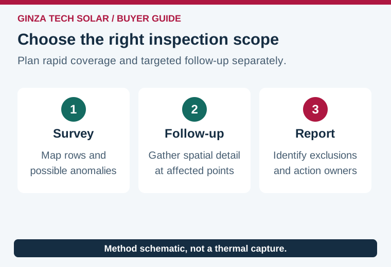
Choose the survey scope before comparing prices
An airborne survey may cover many module rows quickly and create an efficient map for triage. A targeted ground or close-range survey can provide greater spatial detail and access to equipment that is hidden from an aerial view. Compare promised resolution at the target, identification of each observation and the number of verified findings. An image count tells you little about whether a particular cell, junction-box feature or cable termination can actually be examined.
Ask bidders to describe mounting types, rows, inaccessible areas, inverter availability, and any permitted survey exclusions. Have them identify whether modules, junction boxes, combiners and inverter-side connections are part of one scope or separate work. A quote covering the front surface of modules does not establish that concealed connections have been imaged. The IEA PVPS field imaging review compares infrared and electroluminescence (EL) applications and explains the context for locating operating anomalies.
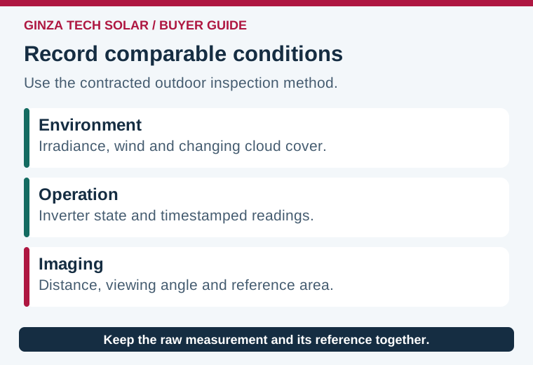
Record what makes a comparison meaningful
| Field record | Why it matters | Ask for |
|---|---|---|
| Plane-of-array irradiance | Heating patterns depend on operating conditions | Time series, sensor location and applicable method |
| Operating state | Unavailable or curtailed equipment can look different | Timestamped inverter or string readings and event logs |
| Weather and view | Wind, cloud changes and reflections can alter apparent patterns | Wind, cloud notes, angle, distance and reference images |
| Equipment identity | Findings must be repeatable and actionable | Row, string, module position, serial where available and orientation |
The IEA PVPS O&M guidelines explain why the plane-of-array measurement and image resolution matter. Have the inspector explain how compliance with the chosen method will be documented and what happens if clouds move through. You may need to repeat part of a survey after an irradiance change. Build that requirement into the quote rather than comparing images collected during clearly different conditions.
Retain the original radiometric files where applicable, together with visible-light images, calibration or measurement settings and the time basis used by the camera. A false-color JPEG alone can hide scale limits and prevent later review. If two screenshots use different color ranges, similar colors do not establish similar temperatures. Arrange for the report to carry a legend, an identified reference area and a clear statement of whether temperatures are apparent or corrected by the inspection method.
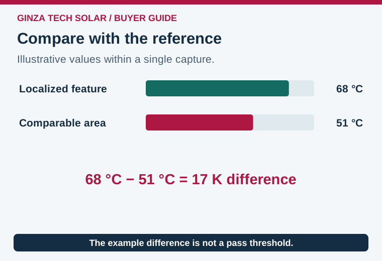
Worked example: compare a pattern with its reference
In a fictional report, an inspector records an apparent temperature of 68°C over a localized feature and 51°C on a comparable nearby region in the same capture. The difference is 17°C, equivalent to 17 K as a temperature interval. The report also records stable operating conditions, matched orientation and a visible image. This example illustrates how the difference is calculated; it does not set a universal pass threshold or assign a fault category.
Now consider a second image showing a similarly bright patch, taken after a cloud front and from a more reflective angle. Before comparing the two observations, verify the scale, capture settings, surrounding conditions and operating state. A visible reflection may move when the viewing geometry changes. Have the inspector flag ambiguous images for corroboration under valid conditions. Record whether the anomaly recurs at the same location after the source of ambiguity has been addressed.
Local patterns can arise from several causes, such as shade, deposits, a module feature or an electrical connection. A recurring pattern helps decide what to inspect next, but the purchase decision may depend on evidence beyond temperature. If deposits or shading are suspected, compare the site conditions described in the soiling and cleaning guide. If the issue appears to involve an internal module feature, the EL shipment inspection guide explains what a linked image record can add. Have the inspection and electrical teams agree which follow-up is appropriate.
Specify how observations reach a decision
Define the deliverable around changes the maintenance team can act on. For a module row with repeated localized observations, request a marked array map and individual image references so the crew can return to the same positions. For an electrical enclosure or connector that is within the inspection scope, keep the component identity and its circuit reference separate from module observations. A report may distinguish an isolated feature from repeated patterns across a hardware batch, but any suspected batch relationship needs inventory evidence and confirmation before procurement decisions are made.
Require the report to separate confirmed findings, observations needing further evidence and areas that could not be inspected. Include asset identity, severity under the contracted method, supporting images, recommended review and escalation owner. If there is a potential safety issue, the responsible site operator manages access and response under the approved electrical safety procedure. An image vendor’s classification and an operator’s action decision have different owners.
For warranty or contract review, preserve the baseline, photos, electrical measurements and maintenance history before any corrective work. If the inspector identifies a module only by its row, request a method to match the location to the as-built inventory. Repeat inspection after corrective work should use comparable conditions and should keep the original records. Periodic surveys then become a trendable maintenance record rather than a folder of disconnected images.
What to put in the request for quotation
Choose a reporting sample before comparing bids. Ask every bidder for a fictional or properly shareable example containing both a clearly recorded finding and an excluded area. Check whether you can locate the asset, reconstruct the measurement conditions, read the image scale, and see the recommended follow-up without calling the author. A one-page summary can help management prioritize actions, while the underlying records let technicians compare observations after later work.
State the handoff time and retest rules for interrupted survey work. If a weather window closes halfway through a site, the report should preserve what was covered and which areas need another visit. Agree a process to reconcile the findings with any planned cleaning, module replacement, or electrical investigation, and identify who decides that a repeat survey is justified. This makes the service scope comparable even when the inspection date or equipment availability changes.
Provide the site layout, module count, design and operating conditions, and the question the survey must answer. Request the method, field constraints, raw deliverables, location precision, reporting criteria, examples of incomplete coverage and the retest scope. Define who receives alerts, owns interpretation and closes each follow-up. For an EPC handover, link the inspection outputs to the commissioning evidence register. For a new supply package, review the PV module range and include the required inspection evidence in the project inquiry.