
Quick answer. Choose solar panel mounting clamps using the exact module frame, the module manufacturer’s approved clamp zones and the mounting system’s drawings. Check the rail, clamp, fastener and electrical bonding as one assembly. Frame height alone does not establish fit or load capacity. For a purchase order, request a drawing that shows each clamp location, contact area and approved configuration, plus a BOM counted from the actual row layout.
This worksheet is for an installer or EPC buyer comparing quotations for rails and clamps. It provides two purchasing checks using fictional dimensions and row counts. Obtain approval for the actual module and mounting combination from the responsible designers and suppliers before installation.
What a mid-clamp and end clamp each need to match
A mid-clamp typically secures adjacent framed modules at a shared rail position and sets the gap between them. An end clamp secures a module at a row edge. The geometry and hardware vary by system. Ask for an assembly drawing rather than assuming that a clamp labeled for a nominal frame height fits every module of that height. Look at the face of the frame, available bearing area, clamp depth, interference with the glass or drainage features and the rail attachment detail.
Request the module model code, frame section, drawing revision and installation instructions. Ask the mounting supplier to identify the corresponding clamp part, rail profile, fastener and any approved bonding hardware. Have the electrical designer verify the bonding path, grounding interface and applicability of the proposed system evidence. Mechanical fit and electrical continuity are separate questions. A substitution can affect both.
Read the approved clamp zone with its conditions
| Check | Ask for | Why it matters |
|---|---|---|
| Position and reference edge | Allowed range and whether the dimension refers to clamp center, edge or another feature | Two drawings can look aligned while using different reference points |
| Orientation and support | Allowed long-side or short-side arrangements, rail direction and number of supports | Test conditions and rated loads may change with support arrangement |
| Clamp contact and gap | Approved contact length and overlap, frame section and module spacing | Prevents an assumed fit from hiding insufficient bearing or clearance |
| Fastener and installation | Exact part numbers, torque instructions, rail engagement and inspection method | Preserves the approved assembly and gives the installer a verifiable check |
| Loads and environment | Site design reactions, module load table, roof or ground attachments and corrosion basis | Module attachment and the supporting structure both need verification |
Module manuals often list several methods with different allowable loads. Read the table for the exact module and orientation, and confirm the clamp arrangement used to establish those loads. Separately obtain the rail spans, attachment and substrate checks from the mounting designer. A module test load does not determine the permitted load on a roof connection, and it cannot be used alone as the site design value. Resolve any conflict between the module manual, rack documentation and site drawing before ordering.
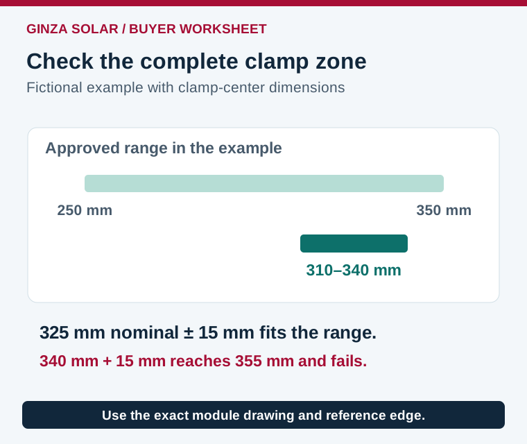
In a fictional example, the module manual permits a clamp-center location 250 to 350 mm from the stated reference end for one arrangement. The draft rail drawing places the clamp center at 325 mm with a ±15 mm location tolerance. The resulting 310 to 340 mm interval fits that fictional zone. A design center at 340 mm with the same tolerance can reach 355 mm and fails this simple check. The numbers illustrate tolerance review. Use the actual limits, measurement reference and tolerances from the approved drawings.
Count clamps from rail lines and row breaks
Assume a fictional array has four independent rows of 12 framed modules. Each row has two continuous rail lines, each adjacent module pair shares one mid-clamp per rail line, and each row end takes one end clamp per rail line. On one rail line there are 11 shared gaps and two ends. Across eight rail lines the starting count is 88 mid-clamps and 16 end clamps, before spares or special parts. This is a BOM screen for the stated attachment method.
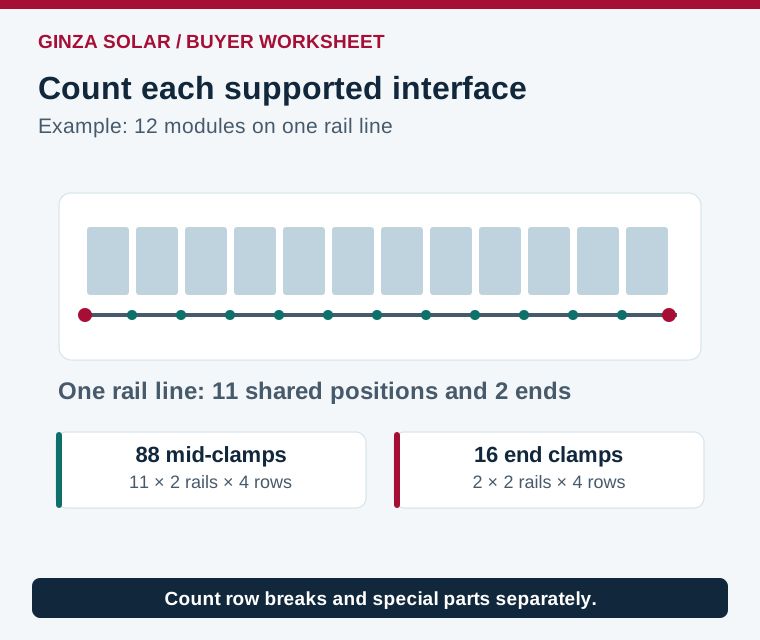
If a 12-module row splits into two independent six-module groups on both rail lines under the same attachment method, each line has ten shared gaps and four ends. Across the two lines for that row, the split removes two mid-clamps and adds four end clamps. Check the actual separation and assembly detail. Gaps for access, rail expansion, changes in orientation, splices and changes in support can affect the counts or require dedicated parts. A module count by itself cannot define rails, anchors, bonding jumpers, cable clips or roof attachments.
Before buying, close the interface gaps in writing
Confirm the documented electrical scope separately using the PV module grounding and bonding checklist, especially when a rail splice or substituted clamp has a bonding function.
- Send the exact module information. Include model, revision, frame detail, manual and the intended mounting orientation.
- Send the site design basis. Include the dimensioned layout, support surface, local loads, edge zones, site exposure and available attachment details.
- Request a marked-up drawing. The drawing should show clamp positions, orientation, reference edges, rail and attachment spacing, row breaks and any maintenance clearances.
- Require a part-by-part BOM. Compare mid and end clamps, fasteners, rail and splice parts, approved bonding components, cable support and agreed spares. Identify exclusions.
- Agree how substitutions are approved. Review module and rack revisions again when either side changes. Record updated drawings, torque instructions and acceptance checks with the purchase record.
At handover, ask for the installed position and torque checks required by the approved system, the fastener records where applicable and evidence of bonding and grounding checks. A representative trial assembly can help expose connector, tool access or frame interference before a bulk order. Have the project team evaluate it against the approved mechanical and electrical criteria. A trial fit by itself does not prove the assembly meets the site design loads.
Before releasing the purchase order, ask the two suppliers to sign off on the same drawing revision. Put the model and frame code, clamp and rail part numbers, approved orientation, clamp reference dimensions and any conditional load limits on that record. If a proposal covers several roof zones, identify which details apply to each zone. Check whether row-edge conditions or a different substrate change attachment quantities. During receiving, compare the packing labels and sample assemblies with the released BOM, and set aside mismatched components until the designer confirms an approved replacement. This is especially useful when the clamp package arrives before the modules or different contractors supply the two assemblies.
For the wider supply package, see the solar mounting system comparison and PV project BOM checklist. If rear-side yield matters, document any rails and cable trays that shade the module rear in the bifacial gain review.
Frequently asked questions
Are all clamps for a 30 mm module interchangeable?
Match the exact frame profile, clamp engagement, contact area, rail and approved combination. Nominal height is only one input.
Can I move a clamp slightly outside the zone?
Resolve the position with the approved module and mounting documentation. Ask for a reviewed alternative if the layout cannot meet the allowed range.
How many clamps does a solar panel need?
Use the approved support method. Count shared mid-clamps and end positions from the real rail-line layout, including row breaks and special cases.
What torque should the installer use?
Use the current instruction for the exact fastener and clamp assembly and the applicable module restrictions. Ask the supplier to identify the torque basis on the drawing.
References and project quotation
- LONGi installation manuals, examples of model-specific clamping and load tables
- DOE FEMP guidance on PV design, installation and commissioning
Compare GINZA solar mounting parts and request a rail and clamp quotation with the module drawing, proposed layout and project design basis.