
A solar mounting system is the structural framework that secures photovoltaic modules to a roof, the ground, or a purpose-built structure. The right mounting system affects structural safety, installation speed, module orientation, maintenance access, logistics, and the long-term reliability of the entire PV project.
For EPC contractors, project developers, distributors, and commercial buyers, choosing between different solar mounting system types is not simply a question of roof versus ground. The decision also depends on design wind speed, snow load, roof or soil conditions, module dimensions, corrosion exposure, installation labor, project scale, local codes, and supplier engineering capability.
This guide explains the main solar mounting system types, their components and materials, where each configuration works best, which technical standards matter, how costs should be compared, and how B2B buyers can evaluate a solar mounting system supplier before placing a bulk order.
Last reviewed: August 8, 2026.
Quick Answer: Which Solar Mounting System Type Should You Choose?
Choose roof mounting when a structurally suitable building roof is available, fixed-tilt ground mounting when simplicity and predictable maintenance are priorities, and a single-axis tracker when utility-scale yield gains justify added mechanical and control complexity. Use solar carports, floating PV, agrivoltaics, or BIPV only when the site needs their second function and can support project-specific engineering.
Before ordering, confirm the project location, design code, wind and snow loads, roof or soil data, module dimensions, corrosion environment, installation scope, and required certification or listing. No mounting type is universally best; the right choice is the lowest-risk system that satisfies the site and lifecycle requirements.
What Is a Solar Mounting System and Why Does It Matter?
A solar mounting system is the mechanical interface between PV modules and the structure or terrain supporting them. It must keep the array stable throughout its service life while transferring dead load, wind uplift, snow load, and other forces into the roof, foundation, or supporting structure.
A mounting system normally performs four functions:
- Structural support: Holds modules securely under expected environmental loads.
- Module positioning: Maintains the required tilt, azimuth, row spacing, and clearance.
- Load transfer: Transfers wind, snow, seismic, and dead loads into the building or foundation.
- Bonding and grounding support: Provides compatible pathways and hardware where the electrical design requires module and racking bonding.
The mounting package may appear less important than modules or inverters, but it has direct consequences for permitting, installation labor, waterproofing, corrosion resistance, service access, and warranty risk. A low-cost racking quote can become expensive if it requires excessive field modification, uses weak surface treatment, lacks project-specific structural calculations, or arrives with incomplete hardware.
For B2B procurement, the key question is not ?Which mounting system is cheapest?? It is ?Which mounting system meets the project loads, site conditions, installation constraints, and lifecycle requirements at the lowest total installed risk??
Solar Mounting System Components and Materials
Most solar panel mounting systems are assembled from a repeatable set of structural components, although the exact BOM changes by roof type, ground foundation, and module layout.
Typical Components
A commercial solar mounting system may include:
- rails or rail-less module supports;
- mid clamps and end clamps;
- roof hooks, L-feet, standoffs, seam clamps, or hanger bolts;
- ground posts, piles, columns, beams, and braces;
- purlins or module support rails;
- base plates and anchor assemblies;
- concrete ballast trays or blocks for non-penetrating flat roofs;
- fasteners, washers, bonding hardware, and grounding lugs;
- tracker torque tubes, bearings, drive units, controllers, and dampers where applicable.
For procurement teams, the component list should be tied to a project drawing and module layout. A quotation that only provides a price per watt without a detailed BOM is difficult to compare and can hide missing fasteners, extra bracing, ballast, foundation parts, or shipping volume.
Aluminum vs Galvanized Steel vs Stainless Steel
| Material | Main Advantages | Main Limitations | Common Applications |
|---|---|---|---|
| Aluminum alloy | Lightweight, easy to handle, strong corrosion resistance, lower freight weight | Higher raw-material cost than carbon steel | Rooftops, carports, coastal projects, modular rail systems |
| Hot-dip galvanized steel | High strength, cost-effective for large structures, good for heavy sections | Heavier; durability depends on galvanizing quality and cut-edge protection | Ground mount, utility-scale arrays, large carports |
| Stainless steel | Excellent corrosion resistance and fastener performance | Highest material cost | Fasteners, clamps, marine/coastal details, aggressive environments |
Material grade alone is not enough. Buyers should also specify surface treatment, coating thickness where relevant, fastener grade, galvanic compatibility between dissimilar metals, and acceptance criteria for scratches, cut edges, and welding areas.
For hot-dip galvanized fabricated steel, ISO 1461:2022 is a useful international reference for coating properties and test methods. Project specifications may also require local or customer-specific coating standards.
The 3 Main Categories of Solar Mounting Systems
Solar mounting systems fall into three broad categories: ground-mounted systems, roof-mounted systems, and specialized structures such as solar carports, floating PV, agrivoltaic structures, and BIPV support systems.
| Category | Best For | Main Advantage | Main Constraint | Typical Engineering Priority |
|---|---|---|---|---|
| Ground-mounted | Utility-scale and commercial projects with available land | Flexible tilt, row spacing, and maintenance access | Foundations, soil, land use, civil work | Wind, soil/foundation design, corrosion |
| Roof-mounted | Commercial, industrial, and residential buildings | Uses existing roof area and reduces land demand | Roof capacity, waterproofing, attachment compatibility | Roof structure, uplift, membrane/penetration details |
| Specialized | Carports, reservoirs, farms, architectural integration | Combines PV with another site function | Custom engineering and higher structural complexity | Site-specific structural and environmental design |
There is no universally ?best? solar mounting system. The correct choice depends on what the project site allows and which constraints dominate the design.
Ground-Mounted Solar Mounting Systems
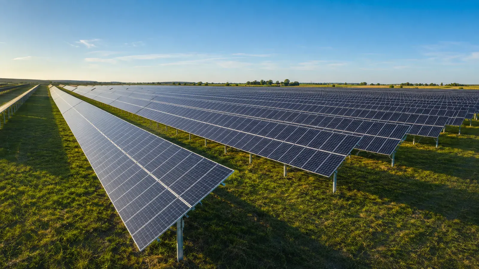
Ground-mounted solar systems are common in utility-scale PV and in commercial projects where sufficient land is available. They offer strong control over tilt angle, row spacing, orientation, drainage, and maintenance access.
Fixed-Tilt Ground Mount Systems
A fixed-tilt solar ground mounting system holds modules at a permanent angle. It is mechanically simple, has relatively few moving parts, and is often the easiest ground-mount configuration to procure, install, and maintain.
Typical foundations include:
- driven steel piles;
- ground screws;
- concrete footings;
- precast or ballasted foundations for sites where penetration is restricted.
Fixed-tilt systems are attractive when project developers prioritize predictable CAPEX, low maintenance, and simple O&M. They are also useful where tracker economics are weakened by irregular terrain, small project size, high wind exposure, difficult maintenance access, or low direct-normal irradiance.
Single-Axis Tracking Systems
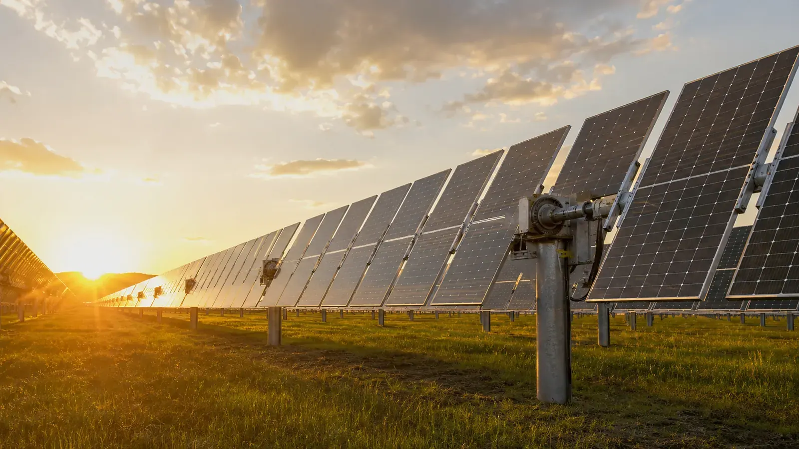
A single-axis tracker rotates module rows along one axis so the panels follow the sun through the day. Compared with fixed tilt, trackers can increase annual energy yield, but the gain is highly dependent on latitude, irradiance profile, terrain, row spacing, backtracking strategy, bifacial design, and availability.
Single-axis tracking is common in large utility projects because additional energy production can justify the extra structure, controls, drives, commissioning work, and maintenance. Bifacial modules are frequently paired with trackers because rear-side irradiance can add further yield when ground albedo and geometry are favorable.
A tracker procurement package should include more than steel tonnage. Buyers should review:
- drive architecture and motor quantity;
- torque tube design;
- stow strategy and wind logic;
- controller architecture and communication;
- backtracking algorithm;
- allowable terrain slope;
- module compatibility;
- bearing and damper design;
- commissioning requirements;
- spare-parts strategy;
- compliance with tracker-specific qualification standards.
For tracker systems, IEC 62817:2014+A1:2017 is the published consolidated international design-qualification standard. It defines test procedures for tracker components and complete tracker systems.
Dual-Axis Tracking Systems
Dual-axis trackers adjust both azimuth and elevation. They can maximize solar incidence more precisely than single-axis designs, but they also require more motors, controls, foundations, moving parts, and maintenance.
As a result, dual-axis systems are relatively uncommon in mainstream utility PV. They are more likely to appear in research systems, concentrator PV, specialty off-grid applications, or high-value sites where land area is limited and energy yield per installed module is more important than structural simplicity.
Pole-Mounted Systems
Pole mounts support one or more modules on a single vertical or near-vertical post. They are useful for small arrays, remote monitoring stations, telecom sites, agricultural equipment, lighting, pumps, or uneven terrain where a conventional table structure would be inefficient.
Pole-mounted designs may be fixed or manually adjustable. Their structural simplicity at small scale can be attractive, but the foundation moment at the pole base can become significant in high-wind areas.
Ground Mount Comparison
| Ground Mount Type | Energy Strategy | Mechanical Complexity | Best Fit | Main Procurement Risk |
|---|---|---|---|---|
| Fixed tilt | Baseline, optimized fixed orientation | Low | Cost-sensitive commercial and utility projects | Under-designed foundations or coating |
| Single-axis tracker | Higher yield through daily tracking | Medium?High | Large utility projects | Controls, drive reliability, wind stow, spare parts |
| Dual-axis tracker | Maximum directional tracking | High | Specialized applications | High CAPEX and maintenance burden |
| Pole mount | Small independent array | Low?Medium | Remote/small systems | Pole foundation and wind moment |
Roof-Mounted Solar Mounting Systems
A solar roof mounting system must match both the roof covering and the underlying structure. The same module layout can require very different attachment hardware on asphalt shingles, clay tile, standing-seam metal, trapezoidal sheet metal, TPO membrane, concrete, or another flat-roof assembly.
Pitched Roof Mounts: Shingle and Tile
Pitched roof systems commonly use roof hooks, standoffs, L-feet, hanger bolts, or other attachments that transfer load into rafters, trusses, purlins, or another structural element.
For shingle and tile roofs, waterproofing details are critical. The attachment must not rely on casual field sealing alone. Flashing, compatible membranes, compression seals, or approved roof-specific components should be used according to the roof system and local code.
Tile roofs also require attention to tile clearance and point loading. Poorly positioned hooks can crack tiles or create uplift problems if the installer modifies components in the field.
Flat Roof Mounts: Ballasted vs Penetrating
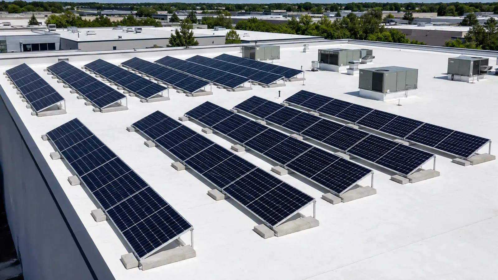
Flat-roof solar mounting systems are usually divided into ballasted and mechanically attached/penetrating designs.
A ballasted system uses weight and aerodynamic design to resist movement without relying primarily on roof penetrations. It can reduce waterproofing disruption and installation steps, but it adds dead load and may not be appropriate where roof capacity is limited or wind uplift is severe.
A penetrating system transfers load through mechanical anchors into the roof structure. It can reduce ballast weight and provide strong uplift resistance, but every penetration must be engineered and waterproofed correctly.
| Flat Roof Option | Main Benefit | Main Constraint | Best Use Case |
|---|---|---|---|
| Ballasted | Minimal roof penetration | Added dead load and ballast logistics | Strong roof structure, membrane roof, moderate wind environment |
| Penetrating | Strong direct load transfer | Waterproofing and attachment detailing | High-wind zones, limited dead-load allowance, engineered roof anchors |
| Hybrid | Balances ballast and anchors | More design coordination | Projects optimizing load and penetration count |
The choice should come from a roof structural review and wind design, not from a blanket rule that ?ballasted is better because it does not penetrate the roof.?
Metal Roof Mounts: Standing-Seam and Corrugated/Trapezoidal
Standing-seam metal roofs can often use non-penetrating seam clamps. This is one of the fastest commercial rooftop mounting methods when the clamp has been verified for the exact seam profile and material.
Corrugated or trapezoidal metal roofs typically use fastened brackets or short-rail systems connected to the roof sheet and/or supporting purlins according to the engineered design. Fastener pull-out, pull-over, sealing washers, sheet thickness, purlin spacing, and corrosion compatibility all matter.
For industrial roofs, a supplier should request roof profile drawings and substrate information before finalizing the BOM. ?Metal roof? is not a complete specification.
Specialized Solar Mounting Structures
Specialized systems solve projects where ordinary roof or ground racking does not fit the site or where PV must serve a second function.
Solar Carports
Solar carports combine a PV support structure with parking shade and can also support EV charging, lighting, drainage, and cable management. Compared with standard ground mount, carports generally require larger columns, deeper or wider foundations, greater clear spans, vehicle-impact coordination, and more architectural attention.
For commercial properties, the additional structural cost can be justified because the project creates usable parking infrastructure rather than occupying undeveloped land.
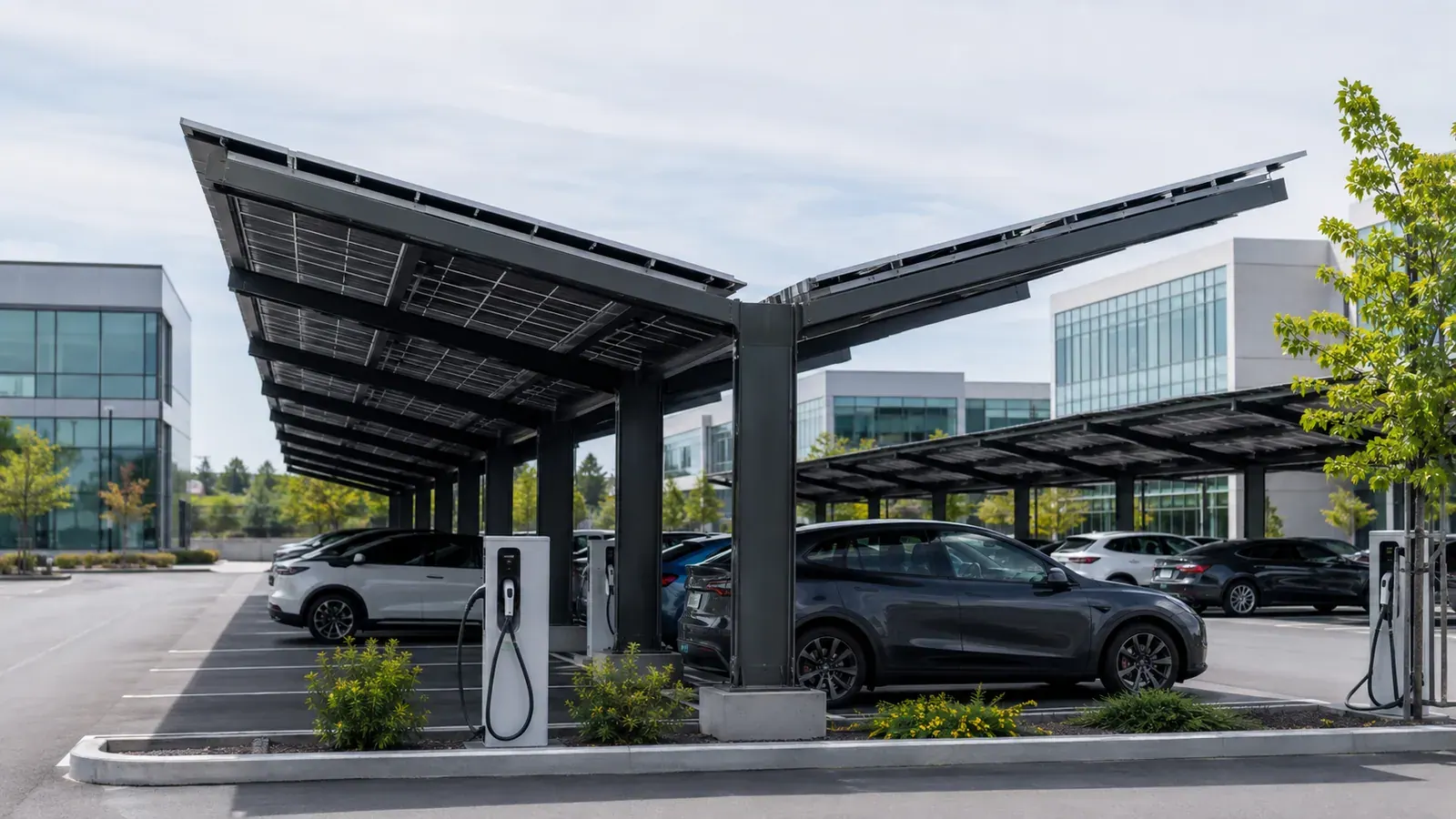
For a deeper review of canopy geometry, foundations, costs, and EV charging integration, see our solar carport mounting systems.
Floating Solar (FPV)
Floating PV systems place solar modules on buoyant platforms installed on reservoirs, ponds, quarry lakes, water-treatment facilities, or other suitable water bodies. Their main advantage is land conservation, and water proximity can reduce module operating temperature and improve energy yield under favorable conditions.
The size of that cooling benefit is site- and design-dependent; it should not be treated as a universal fixed percentage. FPV feasibility also depends on water depth, water-level variation, wind and wave conditions, anchoring geometry, mooring loads, corrosion exposure, cable routing, access, biofouling, and environmental permitting.
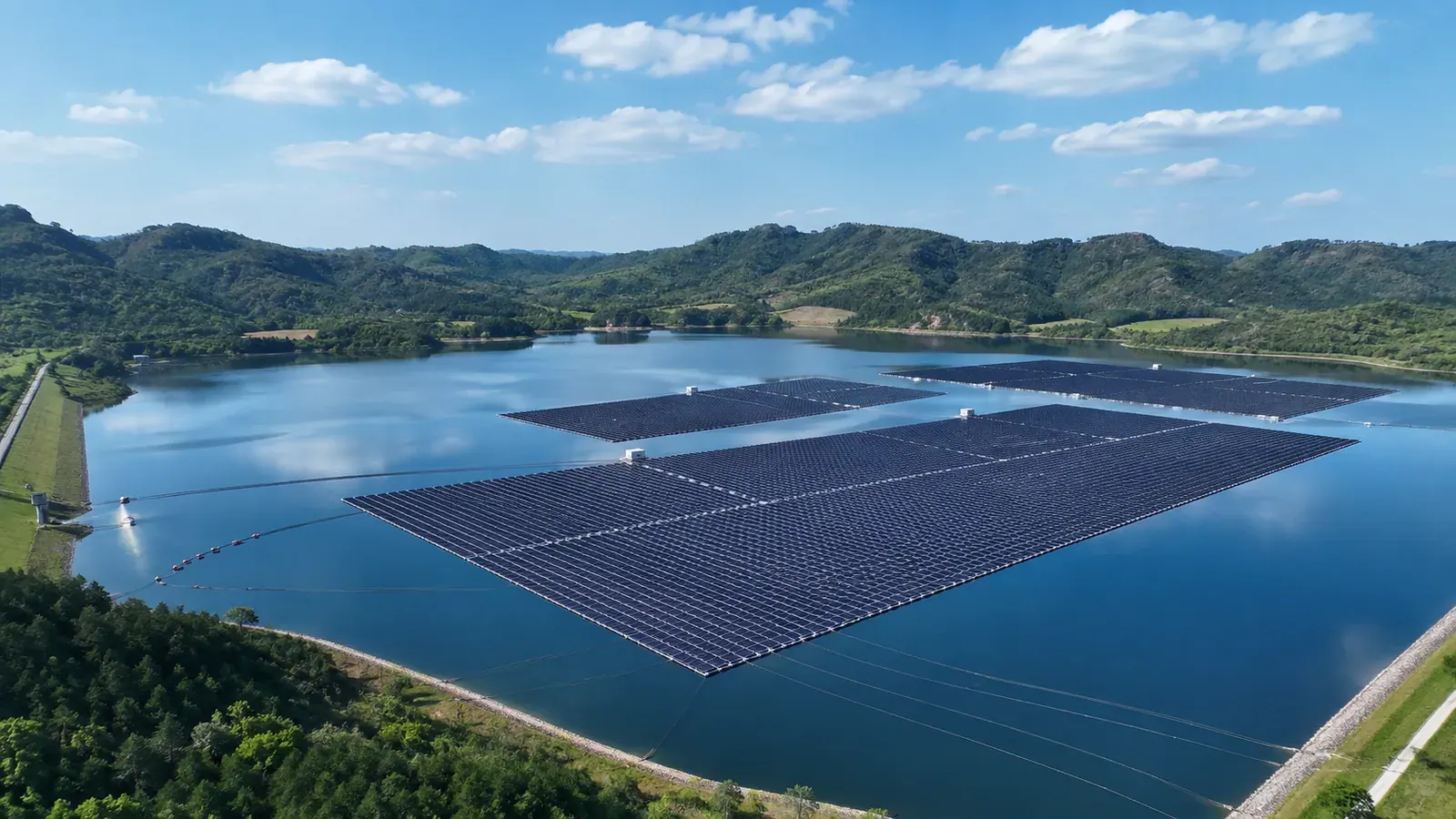
FPV structures typically require:
- UV-resistant float systems;
- module support frames;
- walkways or maintenance access;
- mooring and anchoring systems;
- marine-compatible cable management;
- site-specific hydrological and structural analysis.
The system can be commercially attractive when land is scarce or expensive, but procurement should be based on a complete floating-platform and mooring design rather than the module rack alone.
Agrivoltaic Systems
Agrivoltaic systems combine solar generation with crop production, grazing, or other agricultural activity. Mounting structures are often elevated or spaced to preserve farm operations, light distribution, equipment clearance, irrigation access, or livestock movement.
The optimal structure depends on the crop, climate, machinery, desired shading profile, and farming schedule. This makes agrivoltaic structures more project-specific than standard fixed-tilt ground mount.
Building-Integrated Photovoltaics (BIPV)
BIPV uses photovoltaic products as part of the building envelope, such as roof tiles, facade elements, skylights, or solar glass. The mounting and interface system must satisfy both electrical and building-envelope requirements.
For BIPV, IEC 63092-2 addresses requirements for building-integrated photovoltaic systems and includes aspects related to the intended mounting arrangement and mounting structure.
How to Select the Right Solar Mounting System for a Project
The best solar mounting system is the one that satisfies site constraints, structural loads, module layout, installation requirements, and lifecycle risk with the least unnecessary complexity.
Use the following selection process.
1. Define the Installation Surface
Identify whether the project is on:
- open land;
- a pitched roof;
- a flat membrane roof;
- standing-seam metal;
- trapezoidal/corrugated metal;
- a parking area;
- agricultural land;
- a water body;
- an architectural building envelope.
This immediately eliminates many incompatible mounting types.
2. Confirm Structural Inputs
Before a supplier completes structural calculations, provide:
- project location and coordinates;
- design code and edition;
- basic/design wind speed or required wind pressure;
- snow load where applicable;
- seismic requirements where applicable;
- exposure/topographic category;
- roof height and building dimensions;
- roof construction or soil report;
- module model, dimensions, weight, and orientation.
A generic ?150 km/h wind-resistant? statement is not an engineering calculation. Wind design depends on code methodology, site exposure, height, array position, pressure zones, terrain, and load combinations.
3. Match the System to the Module Layout
Module dimensions continue to increase, and clamp zones, frame strength, portrait/landscape orientation, row length, and tracker compatibility can change the structural design.
Do not finalize the mounting BOM before the module model is confirmed.
4. Evaluate Installation Labor
A lower hardware price can be offset by slower installation. Compare:
- number of components per module;
- pre-assembled parts;
- rail cutting requirements;
- field drilling or welding;
- torque requirements;
- adjustment tolerance;
- packaging sequence;
- special tools;
- crane or lifting requirements.
For EPCs, installation minutes per module can be as important as material price per watt.
5. Consider Corrosion and Environment
Coastal, high-humidity, industrial, agricultural, and chemical environments may need upgraded materials, thicker coatings, stainless fasteners, isolation between dissimilar metals, or project-specific corrosion categories.
6. Check Codes, Permitting, and Product Approvals
The project engineer should identify which structural codes, electrical listing requirements, fire classifications, roof approvals, or local product certifications apply. Requirements vary by market, so a ?global certificate package? is rarely sufficient for every destination.
7. Compare Total Delivered and Installed Cost
Compare equivalent scopes. A useful cost comparison includes:
- structural hardware;
- attachments or foundations;
- fasteners;
- ballast if required;
- engineering;
- packaging;
- inland transport;
- ocean freight;
- duties/taxes;
- site labor;
- lifting equipment;
- expected maintenance and spare parts.
Solar Mounting System Standards and Certifications: What B2B Buyers Should Verify
One of the most common procurement mistakes is treating every standard as if it were a product certificate. Structural design codes, product safety certifications, manufacturing standards, and laboratory qualification standards serve different purposes.
A supplier should be able to explain exactly which document applies to the product and which calculations still need to be completed for the project site.
| Standard / Requirement | Region / Scope | What It Actually Covers | Procurement Use |
|---|---|---|---|
| UL 2703 | North America | Mounting systems, mounting devices, clamps/retention devices, grounding/bonding and rooftop fire classification within the certification scope | Verify the exact listed product, module combinations, functions, and installation conditions |
| ASCE/SEI 7-22 | United States | Site-specific structural loads including wind, snow, seismic and load combinations | Used by the project structural engineer; it is not a supplier ?certificate? |
| Eurocode EN 1991 series | Europe | Actions on structures, including wind and snow provisions | Basis for project-specific structural calculations in many European markets |
| AS/NZS 1170.2:2021 | Australia/New Zealand | Wind actions for structural design | Used for project wind calculations |
| IEC 62548-1:2023+A1:2025 | International PV array design | PV array design requirements, including revised mounting-structure provisions | Useful technical design reference; not a blanket mounting product certification |
| IEC 62817:2014+A1:2017 | Solar trackers | Design qualification and test procedures for tracker systems | Important for single-axis and dual-axis tracker procurement |
| MCS 012 | United Kingdom | Certification scheme requirements for solar mounting systems/components used on building roofs within its scope | Relevant for MCS-compliant UK roof installations |
| ISO 1461:2022 | International | Hot-dip galvanized coatings on fabricated iron and steel | Verify galvanizing specification and test criteria for steel structures |
Important Correction: IEC 62847 Is Not a Solar Mounting Standard
Some online solar content incorrectly cites IEC 62847 as a solar mounting or corrosion standard. It is actually an IEC standard for railway rolling-stock electrical connectors. It should not be requested as evidence of PV mounting compliance.
For B2B purchasing, ask the supplier for the exact report number, issuing body, product model, tested configuration, validity status, and scope. A certificate logo on a brochure is not enough.
Official Standards References
- UL Solutions: PV Mounting Systems Certification and UL 2703
- IEC 62817:2014+A1:2017: Design qualification of solar trackers
- IEC 62548-1:2023+A1:2025: Photovoltaic array design requirements
- IEC 63092-2:2020: Requirements for BIPV systems
- IEC 62847:2016: Railway rolling-stock electrical connectors
- ISO 1461:2022: Hot-dip galvanized coatings on fabricated iron and steel
Solar Mounting System Cost Breakdown
Solar mounting system pricing varies significantly by system type, material, structural loads, foundation method, module layout, order size, coating specification, packaging method, engineering scope, and destination.
For that reason, a single worldwide ?solar mounting system price per watt? can be misleading. B2B buyers should distinguish between:
- ex-factory mounting hardware price;
- FOB/CIF delivered hardware price;
- installed structural BOS cost;
- total project installed cost.
What Drives Mounting Cost?
| Cost Driver | Why It Matters |
|---|---|
| Aluminum/steel market price | Directly changes rail, post, beam, and purlin cost |
| Design wind/snow load | Higher loads require stronger sections, more anchors, or more ballast |
| Foundation type | Driven piles, ground screws, concrete, and ballast have different material/civil costs |
| Coating and corrosion class | Thicker galvanizing or premium materials increase cost but reduce corrosion risk |
| Module size and layout | Changes rail spans, clamp count, table size, tracker torque, and structural loading |
| Pre-assembly | Can increase factory cost while reducing site labor |
| Packing density | Long rails and steel members can dominate container utilization |
| Engineering scope | Stamped calculations, CAD, foundation design, and local engineering can be separate charges |
| Order volume | Larger standardized orders usually improve manufacturing and logistics efficiency |
Compare Quotes on a Like-for-Like Basis
A $/W quote is useful only if all bidders include the same scope. Request a commercial comparison sheet that lists:
- Incoterm;
- module model and layout;
- system type;
- material grade;
- coating specification;
- fastener grade;
- wind/snow design basis;
- foundation or roof attachment scope;
- engineering deliverables;
- warranty;
- packing method;
- container quantity;
- lead time;
- excluded items.
Include mounting hardware in the full project BOM rather than evaluating it in isolation. See our Solar Project BOM Checklist for a broader procurement framework.
Solar Mounting System Installation Best Practices
Good hardware can still fail when field installation is poor. EPC contractors should include installation controls in the procurement and quality plan.
Use Approved Drawings
Installers should work from the final approved layout, structural calculation set, and installation manual. Field crews should not change rail spans, pile spacing, clamp positions, fastener sizes, or ballast quantities without engineering review.
Control Fastener Torque
Over-torque can damage aluminum rails, module frames, threads, or sealing washers. Under-torque can allow slippage or poor bonding. Use calibrated torque tools where the manufacturer specifies torque values.
Protect Roof Waterproofing
Every penetration should follow the approved flashing or sealing method. Roof warranty requirements should be checked before work begins.
Verify Pile and Anchor Installation
For ground mount, record pile depth, refusal conditions, verticality, pull-test results where required, concrete strength, anchor torque, and any field remediation.
Manage Dissimilar Metals
Aluminum, galvanized steel, stainless steel, and copper can create galvanic corrosion risks in the wrong environment. Follow the engineered material combination and use isolation components where specified.
Perform Final QC
A practical mounting-system punch list should verify:
- module clamp position;
- rail alignment;
- fastener torque;
- roof sealing;
- bonding continuity where applicable;
- pile/anchor condition;
- corrosion damage;
- loose or missing hardware;
- tracker movement and stow function;
- labeling and as-built documentation.
B2B Procurement Guide: How to Source Solar Mounting Systems
When sourcing solar mounting systems from a manufacturer, buyers should evaluate the supplier as an engineering and quality partner, not only as a metal-fabrication vendor. A reliable supplier should be able to turn project inputs into a traceable BOM, structural design basis, production plan, inspection criteria, and packing list.
Step 1: Prepare a Complete RFQ
A strong RFQ should include:
- project country and location;
- project capacity in kW/MW;
- roof type or geotechnical information;
- module brand/model and dimensions;
- portrait or landscape orientation;
- tilt angle;
- row/table configuration;
- design wind and snow criteria;
- corrosion/environmental requirements;
- required standards/certifications;
- target delivery date;
- destination port;
- required Incoterm;
- expected warranty;
- drawings or site photos.
The more complete the RFQ, the more meaningful the quotation comparison.
Step 2: Request Quotations From Multiple Suppliers
Compare at least several qualified manufacturers using the same RFQ. Do not compare a fully engineered package from one supplier with a generic price list from another.
Step 3: Review Engineering Capability
Ask for examples of:
- structural calculation reports;
- CAD/shop drawings;
- roof attachment details;
- pile/foundation recommendations;
- tracker layout documents;
- BOM and packing lists.
The engineering team should be able to explain load assumptions and design changes rather than simply sending a standard drawing.
Step 4: Verify Certificates and Test Reports
Request original or verifiable reports, not just logos. Confirm:
- product model covered;
- report number;
- issuing laboratory/certification body;
- standard edition;
- date/status;
- tested module or mounting configuration;
- whether the report covers mechanical load, bonding, fire classification, tracker qualification, coating, or another specific item.
Step 5: Evaluate Samples or a Trial Order
For repeat distribution or large EPC procurement, inspect:
- extrusion dimensions;
- hole spacing;
- coating quality;
- weld finish;
- clamp fit;
- fastener consistency;
- packaging;
- labeling;
- assembly speed.
Step 6: Audit the Factory
An on-site or live video audit can review:
- extrusion/stamping/welding capability;
- galvanizing or outsourced coating controls;
- incoming material inspection;
- dimensional inspection;
- traceability;
- torque/testing procedures;
- finished-goods storage;
- packaging line;
- non-conformance handling;
- production capacity and lead time.
Step 7: Lock Specifications Into the Purchase Contract
The PO or contract should identify material grades, coating requirements, BOM revision, drawings, acceptance criteria, packaging method, warranty terms, delivery schedule, inspection rights, and treatment of non-conforming goods.
Step 8: Conduct Pre-Shipment Inspection
Before container loading, verify quantity, dimensions, finish, labeling, packaging, accessories, documentation, and container loading plan. For large orders, third-party inspection can reduce the risk of discovering problems only after the goods reach the site.
Supplier Evaluation Checklist
| Evaluation Area | What a Qualified Supplier Should Provide | Red Flags |
|---|---|---|
| Engineering | Project-specific drawings and calculation basis | Generic ?fits all projects? drawings |
| Compliance | Verifiable reports with clear scope | Logos or self-declarations only |
| Material quality | Grade certificates, coating records, traceability | No incoming-material records |
| Production | Capacity matched to promised lead time | Unrealistic lead time with no capacity evidence |
| QC | Documented inspection process and records | No measurable acceptance criteria |
| Warranty | Clear structural/product warranty terms | Broad exclusions that remove practical coverage |
| Logistics | Packing list, container plan, protected long components | Loose mixed hardware and poor labeling |
| References | Verifiable completed projects or customers | No reference projects in similar conditions |
MOQ and Wholesale Orders
There is no universal MOQ for solar mounting systems from China. Standardized rooftop rail products may support relatively small trial orders, while custom ground structures, carports, and trackers typically require project-based quantities because tooling, engineering, steel processing, and packing are configured around a specific layout.
Instead of asking only ?What is your MOQ??, ask suppliers for three tiers:
- sample/trial order quantity;
- distributor stocking MOQ;
- project MOQ or price break by MW.
This creates a more useful commercial comparison.
Shipping and Logistics
Mounting systems are logistics-sensitive because rails, posts, beams, and purlins can be long and bulky. Packaging should protect anodized aluminum surfaces, galvanized coatings, threads, and small hardware while maximizing container utilization.
Ask for:
- package dimensions and gross/net weight;
- pieces per bundle/carton;
- container loading quantity;
- pallet or steel-frame details;
- waterproof protection;
- label format by array/zone;
- spare hardware quantity;
- unloading requirements at destination.
Good packing reduces both damage and installation time because crews can receive material by roof zone, table, or construction sequence.
Common Procurement Mistakes
Avoid these frequent B2B errors:
- selecting only by the lowest $/W price;
- accepting a standard drawing without project-specific load inputs;
- treating ASCE, Eurocode, or another design code as a product certificate;
- requesting the wrong IEC standard;
- ignoring roof profile or soil information;
- failing to specify coating and corrosion requirements;
- approving module substitutions without rechecking clamp zones and loads;
- overlooking packaging and container utilization;
- skipping sample inspection or pre-shipment QC;
- leaving engineering deliverables out of the purchase contract.
Frequently Asked Questions About Solar Mounting System Types
What are the main types of solar mounting systems?
The three main categories are ground-mounted, roof-mounted, and specialized solar mounting systems. Ground systems include fixed tilt and trackers; roof systems include pitched-roof, flat-roof ballasted/attached, and metal-roof configurations; specialized systems include solar carports, floating PV, agrivoltaics, and BIPV.
What is the best mounting system for solar panels?
There is no single best mounting system. The correct system depends on the installation surface, design loads, module model, project size, corrosion environment, installation labor, local code, maintenance strategy, and budget.
What is the difference between a ground mount and a roof mount?
Ground mounts offer more freedom to optimize orientation, row spacing, maintenance access, and foundations, but they require land and civil work. Roof mounts use existing building area but depend on roof structural capacity, attachment details, waterproofing, and roof geometry.
What is the difference between ballasted and penetrating flat-roof mounting?
Ballasted mounting relies mainly on weight and aerodynamic design and can minimize penetrations, but it adds dead load. Penetrating or mechanically attached systems transfer loads into the roof structure and can improve uplift resistance, but they require engineered attachments and waterproofing.
Do solar mounting systems need UL 2703 certification?
UL 2703 is highly relevant to North American PV mounting products, but buyers must verify the exact certification scope. A UL 2703 listing can cover specific functions and configurations such as mechanical loading, grounding/bonding, and rooftop fire classification. Local permitting requirements determine what is required for a project.
Is IEC 62847 a solar mounting standard?
No. IEC 62847 is a railway electrical-connector standard. For solar trackers, the relevant IEC design-qualification standard is IEC 62817. For PV array design, IEC 62548-1:2023+A1:2025 includes mounting-structure provisions.
How much does a solar mounting system cost per watt?
There is no reliable universal price per watt. Cost depends on whether the quote is ex-factory hardware, delivered hardware, installed structural BOS, or total installed project cost. Wind/snow loads, material, foundation type, coating, module layout, project volume, shipping, and engineering scope can materially change the price.
How long does a solar mounting system last?
A well-designed mounting structure is normally intended to operate for the PV project's multi-decade service life. Actual durability depends on material selection, corrosion protection, installation quality, environment, maintenance, and whether the design loads are appropriate for the site.
Can solar mounting systems withstand typhoons, hurricanes, or heavy snow?
They can when engineered for the applicable site loads and local code. Do not rely on a universal marketing number such as ?150 mph wind resistant? without reviewing the calculation basis, exposure category, roof zone, height, terrain, safety factors, connections, and foundation/attachment design.
What should I ask a solar mounting system supplier before ordering?
Ask for project-specific drawings, structural design basis, material grades, coating specification, BOM, verifiable test/certification reports, MOQ, lead time, warranty, QC plan, packaging details, container loading quantity, project references, and pre-shipment inspection terms.
Get a Solar Mounting System Quotation for Your Project
For a commercial or utility project, send the project location, module model, layout, roof/soil information, design loads, capacity, and delivery destination before requesting a final mounting quotation.
Browse our solar mounting system product range for available configurations, or pair the structure with our solar panel range for a complete project package.
Request a custom quotation for your next project. For the fastest engineering review, include your module datasheet, site drawings, target capacity, roof or geotechnical details, and required delivery date.
Prepared for EPC contractors, installers, distributors, and project buyers evaluating solar mounting systems for commercial and utility-scale procurement.