

Verify PV module grounding and bonding as an approved assembly when specifying racking. The module frame, clamp or bonding device, rail or mount, splices and grounding hardware need to match the design documents and relevant instructions. A clamp that fits mechanically can still be outside the documented electrical combination. Keep the exact module and hardware revisions in the bill of materials so receiving, installation and service teams can verify the supplied parts.
Bonding joins conductive parts to maintain the designed electrical continuity. Equipment grounding connects the equipment to the protective grounding arrangement defined by the project and governing rules. The precise arrangement and vocabulary depend on the jurisdiction. This purchasing checklist is for matching documents and supplied parts. The qualified designer, installer and applicable authority decide the protective arrangement and verification method.
Ask what the document actually covers
UL Solutions’ PV mounting certification overview explains the role of UL 2703 in evaluating mounting, clamping and grounding components. It also describes a distinct assessment of rooftop system fire classification for a specific module and racking system. A supplier should identify which claim it is making, the scope of that claim and the actual listed or evaluated combination. A mark on one part or a general statement covering a product family cannot identify the exact permitted module and hardware configuration.
| BOM item | Check in the evidence | Do before release |
|---|---|---|
| Module frame | Exact model, frame designation and applicable instruction revision | Match the purchase and model markings |
| Rail and clamp | Permitted combination, clamp variant and placement scope | Check both fit and documented bonding function |
| Splice or break | Whether continuity is documented across the intended connection | Have the designer resolve any discontinuity |
| Grounding attachment | Named hardware and design detail for the protective connection | Reconcile the drawing, purchase and installed record |
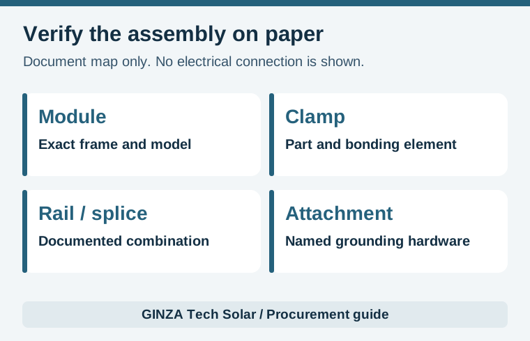
Request the installation guide, allowed module list or frame criteria, affected part numbers and any exclusions. For example, the Canadian Solar module manual, revision 1.21, has separate grounding and mounting sections for the products in its scope. Ask for the current documents for the offered models. A buyer comparing two systems can request equivalent evidence without carrying details from one assembly into another.
Turn each cited document into a line on an evidence register. Useful columns are layout zone, module model and frame version, mounting hardware set, approval reference, instruction section, drawing reference and review status. When the frame or hardware changes, make a new line and identify the zones affected. A dated register also lets the buyer see which approval was current when the purchase was placed, even if the manufacturer later publishes another guide.
Resolve gaps between adjacent components
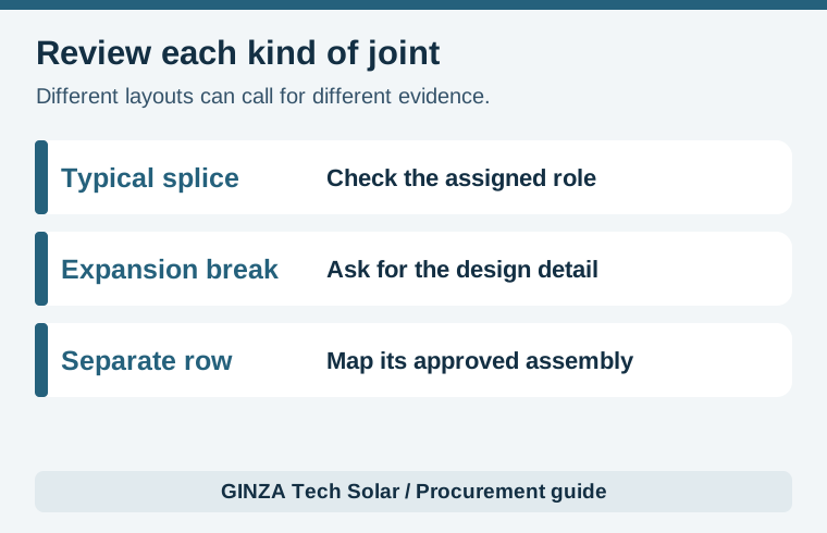
Show the designer the planned boundaries between rail segments and mounting zones. A splice that provides structural support has to be checked for the electrical role assigned to it. Expansion provisions, changes of rail family, separated rows and module orientation can change which components appear in a given detail. Ask for a keyed drawing that distinguishes each typical condition and identifies how the required continuity is maintained at non-typical locations. Avoid a single generic note that leaves every interruption to the field team to interpret.
Also compare the module instructions with the racking instructions. If a manual specifies approved mounting areas, particular clamp constraints or a choice of grounding provisions, the project detail needs to reconcile them. The module mounting clamp guide covers the structural and dimensional questions. Carry both the mechanical and electrical acceptance criteria into the released package, with technical ownership assigned for any conflicting information.
Look for a second issue where the support system changes across the site. One roof zone might use a rail assembly while another uses a different mounting arrangement around an obstruction. Copying the same clamp or protective connection schedule across both zones can obscure the separate approval and design details. Match photographs and inspection records to locations and document which assembly was installed in each zone. Treat a field revision as an engineering question whenever it changes the basis of the accepted detail.
Worked substitution review: a similar-looking clamp arrives
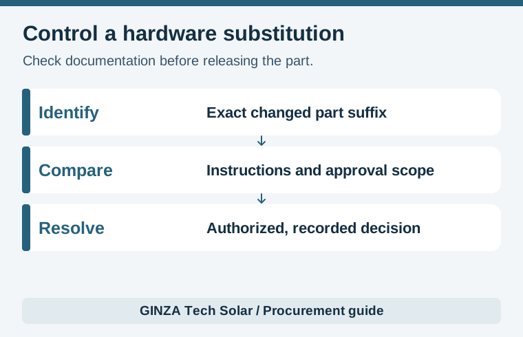
Suppose an approved fictional BOM calls for a particular mid clamp, fastener and bonding element paired with rail R1 and module frame M1. One shipment contains a similar clamp that closes around the frame but has a different part suffix. Fit alone does not resolve the change. Compare the incoming label, model and hardware contents with the latest accepted schedule and ask for evidence covering the newly offered combination before the project accepts a substitution.
The same principle applies to a module substitution. If an alternate module looks the same and has the same nominal wattage, its frame geometry or approval scope may still differ. Keep the original order and record what the substitute actually changes. Have the responsible designer decide whether the original detail remains applicable. If evidence supports a revision, update the drawings, BOM, receiving instructions and inspection record together before the field crew relies on it.
A second fictional variation is a replacement bag labelled with the approved clamp code but containing a different fastener than the accepted assembly. The warehouse can record the packaging discrepancy without deciding whether the parts are electrically equivalent. The buyer should request the vendor’s assembly record and label interpretation. If the hardware has already been issued, the project should identify the locations that may have used it and refer those locations to the responsible reviewer.
Make the verification record useful after handover
Have the project team name the records used at receiving, installation and final inspection. At receiving, confirm identifying labels and quantities. At installation, record the locations covered by the applicable assembly detail and how deviations were closed. For electrical verification, the qualified team should document its approved method, test boundary, relevant measurements and acceptance criteria. A low-resistance reading by itself cannot establish that an undocumented substituted part has the necessary product approval.
Record any special zones, such as an array edge or a place where the hardware changes. Put changes under revision control. When a replacement module or component is ordered years later, a technician should be able to determine what was installed and identify the manufacturer’s supported replacement pathway. The solar commissioning checklist helps organize handover evidence. Maintain supplier correspondence with the design package, especially when an alternate part was introduced after the original approval.
At handover, link the final part schedule to the drawings, inspection scope and disposition log. If an inspector looked only at a sample of rows, say which rows and preserve the sample rationale. Make outstanding items visible with an owner and expected closeout date. Clarity about scope is particularly useful when several subcontractors worked on different roofs or when a later phase uses hardware sourced from an alternate distributor.
Prepare the purchase request with exact module models, the relevant layout and known approval requirements, including the destination market and controlling project authority. If the bidding stage lacks some of those inputs, ask the vendor to show what assumptions it used and what evidence needs design review. Compare GINZA mounting system configurations and send the module, racking and bonding documentation requirements before releasing an order.