
Quick answer. For a simple two-conductor DC circuit, voltage drop is current multiplied by the total outgoing-and-return resistance. Start with the real cable route, conductor data and design current. Then check current-carrying capacity, temperature, grouping, insulation, protection and connectors separately. Passing a voltage-drop target is only one part of choosing a suitable PV cable assembly.
This worksheet helps procurement teams review an engineer’s cable schedule and compare complete quotes. Its simplified copper example illustrates resistance and route length. The electrical designer must select the final conductor and protection using the applicable requirements, equipment instructions and actual installation conditions.
Draw the electrical path and count both conductors
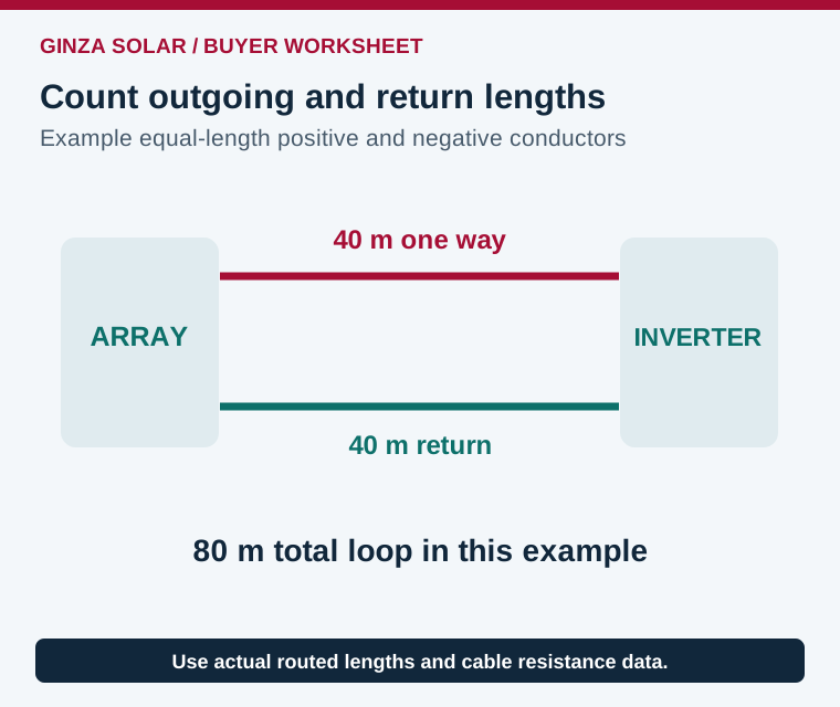
Measure the routed length between the array and inverter or combiner, including vertical sections, detours, service loops and transitions through the building. A distance measured across a roof plan can understate the cable installed. For a simple pair with equal conductor lengths, the loop has twice the one-way route. Use the separate actual lengths if the outgoing and return conductors follow different routes.
Keep the string home run, combined feeder and battery circuit on separate lines. Parallel strings can change current downstream of a combiner, while a battery’s voltage and operating current differ from those of a high-voltage PV string. Match each segment to its own source, length, cable type and protective device. Record where each connector and splice occurs so it can be included in the system review.
Worked example: a 40 m one-way PV route
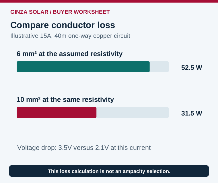
Assume a fictional copper conductor with approximate resistivity 0.0175 Ω·mm²/m at an assumed 20°C reference temperature, a 40 m one-way route, 6 mm² cross section, 15A operating current and 600V at the source. For an equal outgoing and return pair, loop resistance is 2 × 40 × 0.0175 ÷ 6 = 0.233Ω. Voltage drop is 15 × 0.233, or 3.5V, approximately 0.58% of 600V.
The corresponding conductor heat loss is I²R = 15² × 0.233 = 52.5W at that operating point. These are the resistance and voltage-drop relationships explained in Victron’s Wiring Unlimited theory chapter. This simplified result excludes connector resistance and uses an assumed resistivity. Use the actual cable’s resistance data at the relevant operating temperature for the released design. Confirm whether the supplier’s resistance value describes one conductor and convert its units consistently.
| Same illustrative route and current | Loop resistance | Voltage drop | Conductor loss |
|---|---|---|---|
| 6 mm² at the assumed reference resistivity | 0.233Ω | 3.5V, about 0.58% | 52.5W |
| 10 mm² at the same reference resistivity | 0.140Ω | 2.1V, about 0.35% | 31.5W |
Moving to 10 mm² reduces this example’s loss by 21W at the selected current. That does not establish annual savings or the final cable size. Calculate the time-dependent current and value of recovered energy, then include the cost and suitability of terminals, connectors, routing and handling. A shorter approved route can also reduce resistance and material use.
Use operating conditions for loss, design conditions for limits
Voltage drop and heat loss vary with current, and conductor resistance changes with temperature. Evaluate the conditions required by the design method. The operating-current case used for energy loss may differ from the maximum-current case used to size conductors and protection. Bifacial module exposure can also affect the current that the engineer must consider.
For the example’s 0.233Ω loop, raising current from 15A to 20A would increase voltage drop to about 4.67V. Conductor loss rises to about 93.3W because it follows current squared. This is a sensitivity calculation, not permission to run the selected cable at 20A. It shows why a designer needs the actual current profile and maximum design conditions before comparing losses or accepting the cable schedule.
Check whether parallel circuits have equal routes and how combined current changes after a junction. A quote that prices all segments at the string current can understate the requirements of a shared feeder. Document polarity, termination positions and the exact points where circuit quantities change. If a proposed route is revised during construction, update the length and installation factors, have the designer assess the changed circuit and amend the cable takeoff. Preserve the revised drawing so a later expansion does not rely on the shorter route from the original estimate.
For the 600V example, a 3.5V drop is a small fraction. The same absolute drop in a low-voltage battery circuit would be much more significant. It may affect inverter input voltage or charging behavior as well as energy loss. Avoid copying a PV home-run conductor into a 51.2V battery connection. Review the exact battery and inverter installation instructions and their permitted connections.
Check the installation factors that a spreadsheet can miss
Give the designer the ambient and expected conductor temperatures, roof exposure, conduit or tray arrangement, grouping, insulation rating and terminal temperature limits. Check how many loaded circuits share a route and whether cable passes through insulation or enclosed spaces. The permissible current of a given cross section depends on those conditions. Confirm the approved maximum system voltage and environmental ratings of the actual cable.
Review connectors as a specified assembly. Ask for manufacturer and part numbers on both mating halves, supported conductor sizes, tooling, assembly instructions and evidence required by the project. A similar physical shape or a broad compatibility claim should not substitute for an approved mating combination. Contact resistance, poor crimping and loose connections can create local heating that a bulk conductor calculation misses.
Turn the cable calculation into an orderable BOM
Give the receiving team the approved plug and socket part numbers at each interface. The PV connector pairing checklist covers identification and substitution review separately from conductor sizing.
- Label every route and circuit on the drawing, with one-way lengths and the method for spare length.
- State cable type, material, cross section, resistance basis, voltage rating, insulation and environmental requirements.
- List connectors, terminals, glands, labels, supports and any approved splices as separate parts.
- Reference the current, temperature, grouping, voltage-drop and protection checks for each segment.
- Require supplier approval before replacing a cable or connector with a different product.
For receiving inspection, compare reel labels, markings, lot numbers and delivered lengths with the released schedule. Preserve the cable and connector data sheets with the installation records. Have the commissioning plan specify the appropriate continuity, polarity, insulation and connection checks, test equipment and qualified personnel. These tests need a procedure suitable for the connected PV and electronic equipment.
A useful quote includes both the engineering schedule and the commercial quantities. Route takeoff, installation allowance, wastage and spares should be visible so the buyer can compare bids. The PV project BOM checklist connects cables with the rest of the equipment. Use the string sizing worksheet for voltage and tracker-current inputs and the mounting interface guide for cable support around rails and modules.
Frequently asked questions
Do I double cable length in a DC voltage-drop calculation?
For an equal-length positive and negative pair, include both conductors. Use the actual separate lengths when the routes differ.
Does a low voltage-drop result prove the cable is suitable?
Also check permissible current, installation conditions, insulation, voltage, protection and terminations using the applicable design method.
Can I calculate drop from nominal module watts?
Use the relevant circuit current and voltage, the cable route and resistance at the selected condition. A wattage label alone is insufficient.
What is needed for a cable quotation?
Send the circuit schedule, route drawing, design current, cable and connector specifications, required lengths and destination.
References and project quotation
- Victron Wiring Unlimited, DC cable selection and connections
- Victron Wiring Unlimited, resistance and voltage-drop principles
Review GINZA solar project material supply and request a BOM quotation with the released electrical schedule and project information.