
Quick answer. Verify the exact plug and socket as an approved pair before purchasing solar panel connectors. Use the equipment documentation and connector maker’s mating instructions for the actual manufacturer, family and part numbers on each side. A matching silhouette, generic MC4-style description or standalone certification for each half does not establish that a pair is authorized for the project.
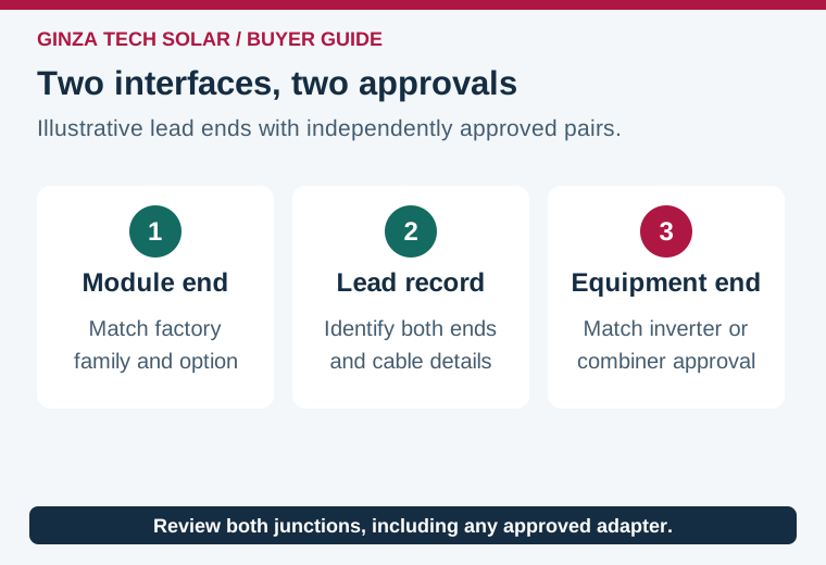
For procurement, keep a schedule at each physical interface: module to module, module string to extension lead, lead to combiner or inverter, and any approved adapter. The design team needs documented compatibility and the required site ratings. The project buyer translates those conditions into orderable part numbers and handles substitutions with the responsible engineer. This article focuses on records and procurement decisions; qualified crews should work under the equipment instructions and approved electrical procedures.
What the connector label tells you
The module’s installation instructions and visible connector markings provide a starting point. Identify the manufacturer and product family. Read the model or option suffix on the specific equipment offered, and request the current version of the instructions. A datasheet may list more than one factory connector option. In that case, make the chosen option explicit in the purchase order and verify it during receiving. A photo from a different production lot cannot settle the identity of the ordered part.
Compare both halves of each connection. The inverter-side approved combination may differ from the module end of an extension lead. An approved preassembled lead with documented different families at opposite ends can be evaluated as two separate mating interfaces. Each interface still requires its own approved pair, and both ends must meet the relevant specifications. The PV fire safety guideline hosted by the U.S. Department of Energy discusses manufacturers’ restrictions on cross-mating and the importance of documented assembly requirements.
Turn the pairing rule into a purchasing record
| Field | Evidence | Buyer action |
|---|---|---|
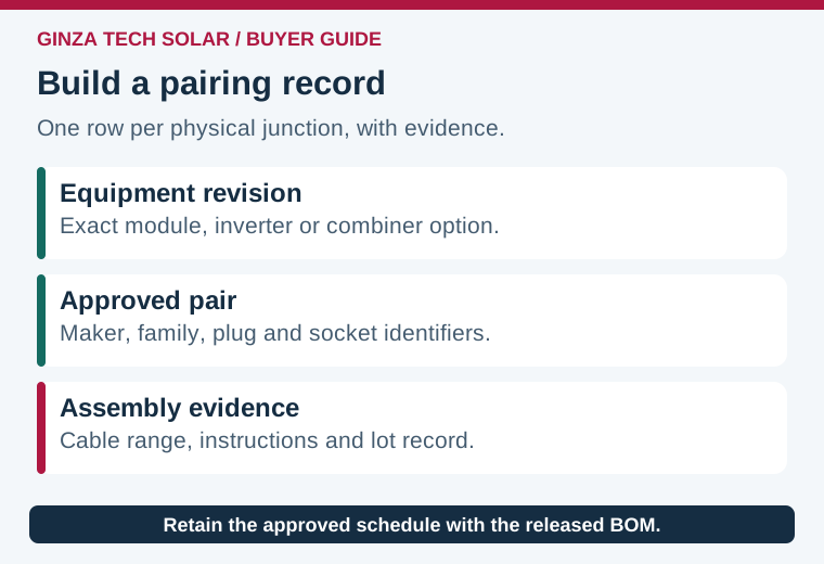
| Equipment and revision | Label, installation instructions, purchase option | Match the item issued for the project |
| Pair identity | Manufacturer, family, plug and socket part numbers | Verify the approved combination for each interface |
| Cable fit | Documented conductor and insulation ranges | Check the offered cable and assembly against the instructions |
| Ratings and environment | Electrical, environmental and installation conditions | Have the designer review suitability for actual service |
| Traceability | Lot labels, assembly instructions and change notice | Keep revisions and evidence with the released BOM |
Ask the supplier to name the documented crimp system or factory assembly method, the approved cable details and the inspection records required for the order. Do not infer suitability from conductor area alone. Cable construction and jacket dimensions affect fit, sealing and strain relief. For conductor sizing separately, use the DC cable voltage-drop worksheet. A correct conductor loss calculation cannot establish connector mating or assembly suitability.
Record the applicable manuals, their revisions and the paths to the supporting evidence. If the connection involves product certification or a local electrical requirement, ask the project team to identify the applicable edition and review the exact assembly; the field use case can differ from a supplier’s document for one connector product. Sandia’s PV connector field study identifies cross-mating, loose connections and connector make and model as details to capture when assessing field reliability.
Worked example: a substitute appears on a shipment
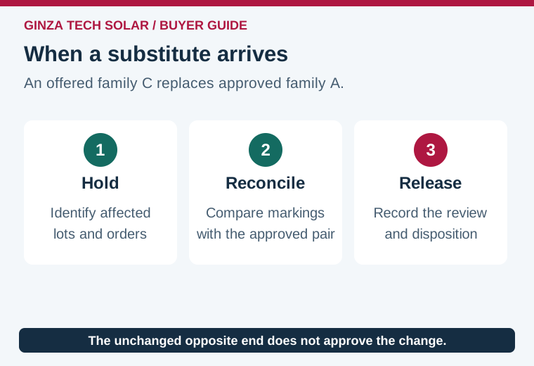
In a hypothetical order, a module option specifies family A. The extension lead is approved with family A on that end and family B on the inverter end, based on documentation from the respective manufacturers and the project design. The incoming package shows family C on the module end, although the supplier describes it as fitting family A. The problem is at the module-to-lead interface. Approval for family B at the other end has no bearing on the changed mating pair.
Place the affected items on hold under the project’s receiving procedure. Compare the stamped identifiers and supplier packing list to the released BOM, confirm the number of affected leads and ask for either the specified items or a formally reviewed design change with the necessary compatibility evidence. Record the disposition by lot. If equipment or leads were already installed, have the responsible site team assess the affected locations and decide how to review them safely. Do not assume all similarly packaged units use the same part.
If there is an acceptable design change, update the appropriate equipment document, drawings, interface schedule and receiving guide. Make sure the replacement parts ordered for later service follow the same record. A substitution resolved only in an email can be missed when the next delivery arrives months after commissioning. Include the revision in the packing labels or inspection reference so people on site know which document governs the assembly.
Keep the change scoped to the affected interface. In the fictional example, suppose only one pallet of preassembled leads is affected. The site team can reconcile that pallet with lot records and verify what other orders used the same part. If one label is illegible, the absence of a reliable identity is itself a documentation issue. Ask the supplier for authenticated lot or assembly records instead of matching the connector by shape. A named owner should release the affected material only after the record and equipment instructions support the decision.
Receiving and handover questions
Decide at ordering whether a connector is supplied already attached to equipment, as a factory-made lead, or as a part for qualified field assembly. These options shift responsibility. For a factory-made lead, ask who documents the completed assembly and correct lead end identification. For approved field assembly, agree who provides the exact assembly documents, tooling requirements and evidence required by the contract. If the equipment vendor will check its own end only, the installer or sourcing team still needs a documented owner for the remaining junction.
Maintain distinct stock records where projects use more than one approved family. A common storage bin and a shared label such as PV connector can erase the information needed during maintenance. Record which part and revision was issued to each project, keep unopened packaging where relevant, and link the receiving record to the approved schedule. This helps when replacement purchases come from a different distributor or the original order has several module variants.
Ask how incoming connector identities will be checked, whether photos are representative or lot-specific, and how mixed lots are separated. Keep a sample pairing record so staff can compare markings without relying on memory. Check whether the module, finished lead and inverter shipments will arrive at different times. That may change when both sides can be checked together and who is responsible for the final installation decision.
At handover, keep records of approved substitutions and attach them to the final project BOM. Information on support and routing belongs with the module mounting and cable-support interface. If a thermal finding later appears near a connector, record its exact location and follow the project inspection process. A thermal image by itself does not identify the connector model or prove what happened during assembly.
To request a GINZA project material quote, include the module and inverter options, drawings, lead ends, required lengths and the exact pairing evidence you expect. Send the interface schedule and BOM so the quotation can state which part numbers and approved assembly scope are included.