
Quick Answer
A solar battery BMS (Battery Management System) is the electronic control system that monitors battery cells, enforces protection limits, estimates State of Charge (SoC), manages cell balancing, and communicates operating limits to an inverter, PCS, or EMS. In lithium solar storage, the BMS is a core safety and control layer rather than a simple voltage protection board.
For B2B buyers, the practical question is not only whether a battery “has a BMS.” The more important questions are whether the BMS matches the battery chemistry and cell configuration, can safely handle the required current, communicates correctly with the exact inverter model, records useful diagnostic data, and is integrated into a battery system with the documentation required for the target market.
This guide explains what a solar battery BMS does, how it works, how to evaluate a 48V or 51.2V LiFePO4 BMS, what to check for CAN and RS485 communication, and how EPCs and wholesale buyers should review BMS requirements before procurement.
What Is a Solar Battery BMS and Why Does It Matter?
A solar battery BMS supervises the cells inside a rechargeable battery pack. It measures cell voltage, pack current, and temperature; applies charge and discharge limits; balances cells; estimates remaining energy; and reports battery status to other equipment.
The BMS should not be thought of as another device placed “after” the battery in the power-flow path. It is integrated into the battery pack or battery rack and continuously supervises the battery while the inverter or PCS moves energy into and out of the pack.
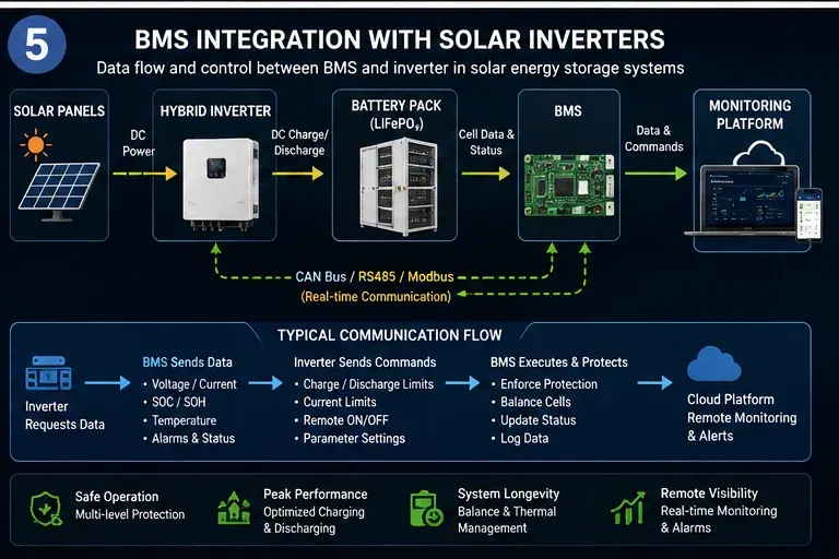
A simplified solar-plus-storage architecture looks like this:
Solar array → inverter/charger or PCS → battery pack → loads/grid
Battery BMS ↔ inverter/PCS/EMS/monitoring platform
The power electronics control energy conversion. The BMS controls what the battery is allowed to do safely.
Residential vs Commercial BMS Requirements
| Procurement Area | Residential / Small System | Commercial / B2B System |
|---|---|---|
| Battery architecture | Usually one or several low-voltage modules | Multiple modules, racks, or high-voltage battery strings |
| BMS hierarchy | Often one BMS per battery | Module BMS + rack/master BMS may be required |
| Communication | CAN, RS485, Bluetooth, local display | CAN/RS485 plus EMS, PCS, gateway, Ethernet or cloud integration |
| Diagnostics | Basic alarms and SoC | Cell-level trends, event logs, rack alarms, remote diagnostics |
| Redundancy | Limited | More important as project scale and consequence of failure increase |
| Documentation | Datasheet and installer manual | Datasheet, protocol information, test reports, compliance documents, commissioning records |
| Buyer focus | Basic compatibility and usability | Safety, repeatability, integration, serviceability, documentation and lifecycle support |
For B2B procurement, “smart BMS” is not a sufficient specification. Buyers should request measurable parameters: supported cell count, continuous and peak current, protection thresholds, balancing current, sensor count, communication interfaces, supported inverter protocols, event logging, firmware control, and compliance documentation for the complete battery product.
For broader battery selection, see the LiFePO4 battery selection guide.
How a Solar Battery BMS Works
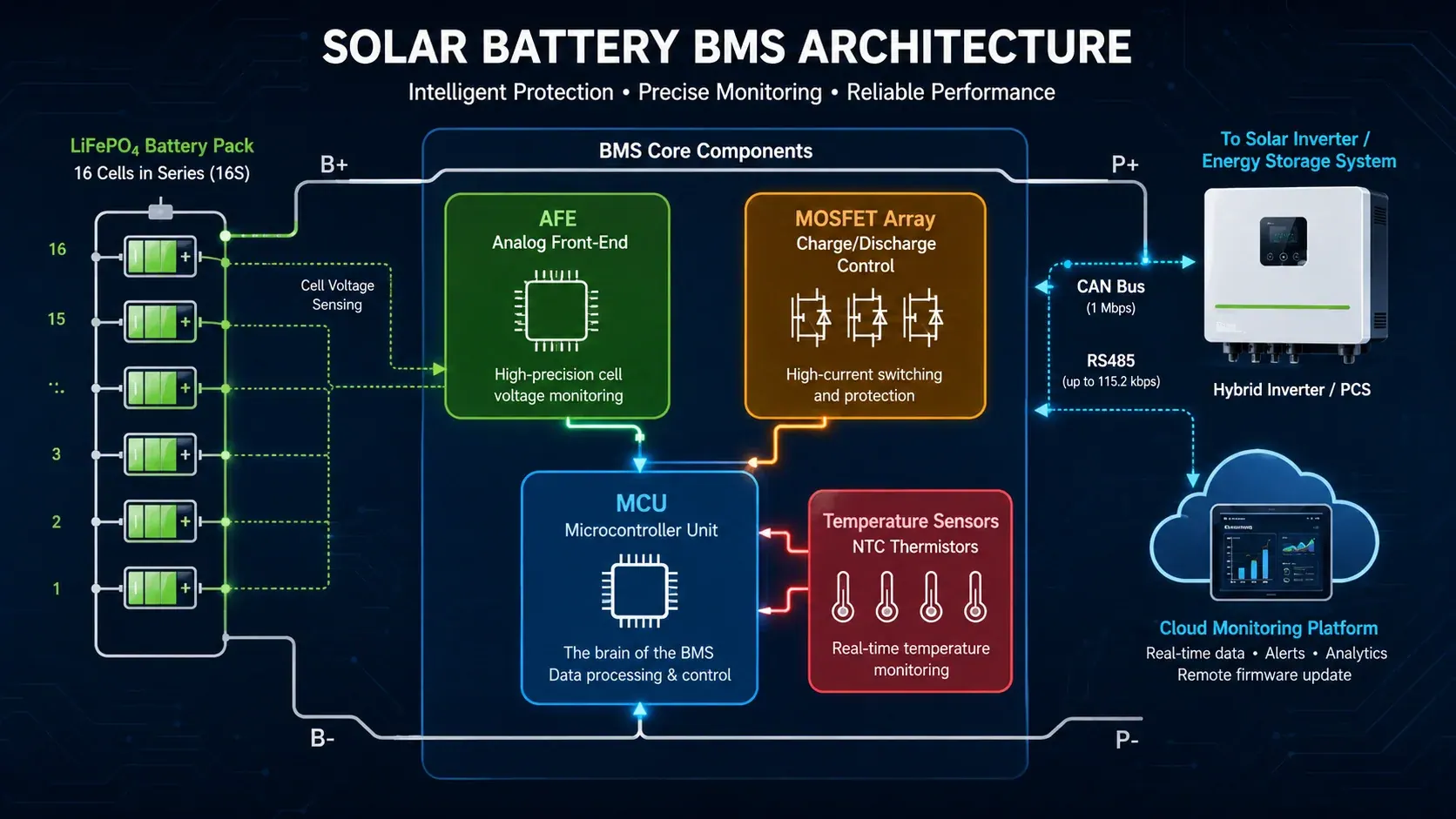
A solar battery BMS continuously measures battery conditions and converts those measurements into protection decisions and operating limits. A typical architecture includes an analog front end (AFE), a microcontroller, current sensing, temperature sensing, switching or contactor control, communication interfaces, and firmware.
1. Analog Front End (AFE)
The AFE measures individual cell voltages and often supports temperature inputs and cell balancing control. Accuracy depends on the specific IC, calibration method, PCB design, wiring, temperature range, and measurement conditions.
For example, modern battery-monitor ICs such as the Texas Instruments BQ76952 support multi-cell voltage monitoring, current measurement, temperature sensing, protection functions, and host-controlled or autonomous balancing. Buyers should therefore avoid generic claims such as “every quality BMS measures to ±5 mV.” Instead, request the actual BMS measurement specification and the conditions under which it is guaranteed.
2. Microcontroller (MCU)
The MCU runs the BMS firmware. Typical responsibilities include:
- SoC estimation
- State of Health (SoH) estimation
- protection logic
- charge/discharge current limits
- balancing control
- fault logging
- communication with the inverter or PCS
- firmware configuration and updates
The quality of BMS software matters as much as the hardware. Two BMS products using similar AFE chips can behave very differently because of firmware, calibration, protection logic, communication protocol implementation, and fault recovery strategy.
3. Current Sensing
A shunt resistor or Hall-effect sensor measures pack current. Current measurement is used for overcurrent protection, SoC calculation, power calculation, cycle counting, and charge/discharge control.
For procurement, ask for:
- continuous current rating
- peak current rating and allowed duration
- current measurement range
- current measurement accuracy
- overcurrent trip thresholds and delay times
4. Temperature Sensing
NTC thermistors or other temperature sensors can monitor cells, busbars, MOSFETs, contactors, and the battery enclosure. The BMS uses these inputs to reduce or stop charging and discharging when temperatures exceed the battery manufacturer's operating limits.
Do not copy one universal temperature window into every project specification. Charging and discharging limits depend on the cell chemistry, cell supplier, pack design, heating system, cooling system, and warranty conditions.
5. MOSFETs, Contactors, and Pre-Charge Control
Low-voltage battery packs often use MOSFET-based switching. Larger battery systems commonly use contactors, fuses, pre-charge circuits, and additional isolation monitoring.
Pre-charge is especially important when connecting a battery to an inverter or PCS with large DC-link capacitors. It limits inrush current before the main contactor closes.
BMS Communication: CAN, RS485, Modbus, RS232 and Ethernet
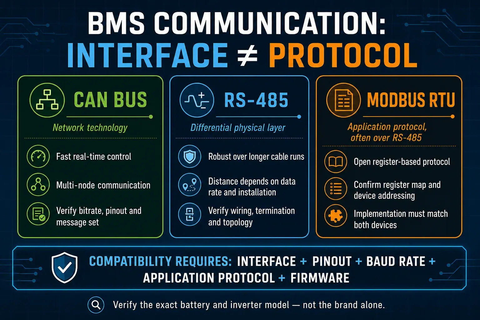
Communication is one of the most misunderstood parts of solar battery compatibility. CAN or RS485 alone does not guarantee that a battery and inverter can communicate. The physical interface, wiring, baud rate, message format, protocol version, inverter firmware, and battery firmware must all match.
Communication Protocol Comparison
| Interface / Protocol | Common Role | Key Procurement Point |
|---|---|---|
| CAN bus | Closed-loop battery-to-inverter/PCS communication | Confirm exact application-layer protocol and CAN pinout, not only “CAN supported” |
| RS485 | Robust differential serial physical layer | Data rate and usable distance depend on cable, termination, topology and transceiver design |
| Modbus RTU | Application protocol often carried over RS485 | Confirm register map, device address rules and inverter/EMS implementation |
| RS232 | Local service/configuration on some batteries | Usually short-distance point-to-point service connection |
| Ethernet / Modbus TCP | Rack gateway, EMS, SCADA or cloud connection | Useful for commercial monitoring and system integration |
| Bluetooth / Wi-Fi | Local app or gateway connectivity | Convenient for setup; should not replace project-grade closed-loop control |
RS485 is designed for robust differential communication and can support long cable runs, but maximum data rate and maximum distance should not be presented as if they are always achievable at the same time. Cable quality, termination, electromagnetic noise, topology, grounding and transceiver selection all matter.
For inverter matching, the safest rule is simple: verify compatibility by exact inverter model and firmware, not by brand name alone. GINZA's existing inverter compatibility guide uses this model-level review approach.
7 Critical Solar Battery BMS Functions to Evaluate
The seven most important BMS functions for solar energy storage are cell monitoring, charge/discharge protection, cell balancing, thermal management, SoC estimation, SoH/diagnostic tracking, and fault handling with safe shutdown.
Function 1: Cell Voltage Monitoring
The BMS measures each cell or parallel cell group rather than relying only on total pack voltage. This matters because one weak or imbalanced cell can reach a protection limit before the rest of the pack.
Buyers should request:
- cell-voltage measurement accuracy
- sampling/update interval
- overvoltage and undervoltage thresholds
- alarm thresholds versus shutdown thresholds
- recovery logic after a protection event
Function 2: Charge and Discharge Protection
A BMS should protect against electrical operating conditions that can damage the battery or create a safety hazard. Typical functions include:
- cell overvoltage protection
- cell undervoltage protection
- charge overcurrent protection
- discharge overcurrent protection
- short-circuit protection
- pack overvoltage/undervoltage supervision
- charge and discharge enable/disable control
The BMS should be the final battery safety authority. Normal inverter operating limits should usually prevent the system from repeatedly hitting hard BMS protection thresholds during everyday operation.
Function 3: Cell Balancing
Cell balancing reduces voltage and State-of-Charge differences between cells in a series string. A battery can only charge or discharge safely until the first cell reaches its limit, so persistent imbalance can reduce usable pack capacity.
There are two broad approaches:
| Feature | Passive Balancing | Active Balancing |
|---|---|---|
| Method | Bleeds excess energy from higher-voltage cells as heat | Transfers energy between cells or cell groups |
| Circuit complexity | Lower | Higher |
| Heat generation | Higher during balancing | Usually lower for transferred energy |
| Typical balance current | Often tens to hundreds of mA | Can range from hundreds of mA to several amps depending on design |
| Best procurement metric | Actual balance current and activation threshold | Actual transfer current, operating window and thermal behavior |
| Best fit | Many low-voltage packs with well-matched cells | Systems that benefit from faster energy redistribution or tighter balancing control |
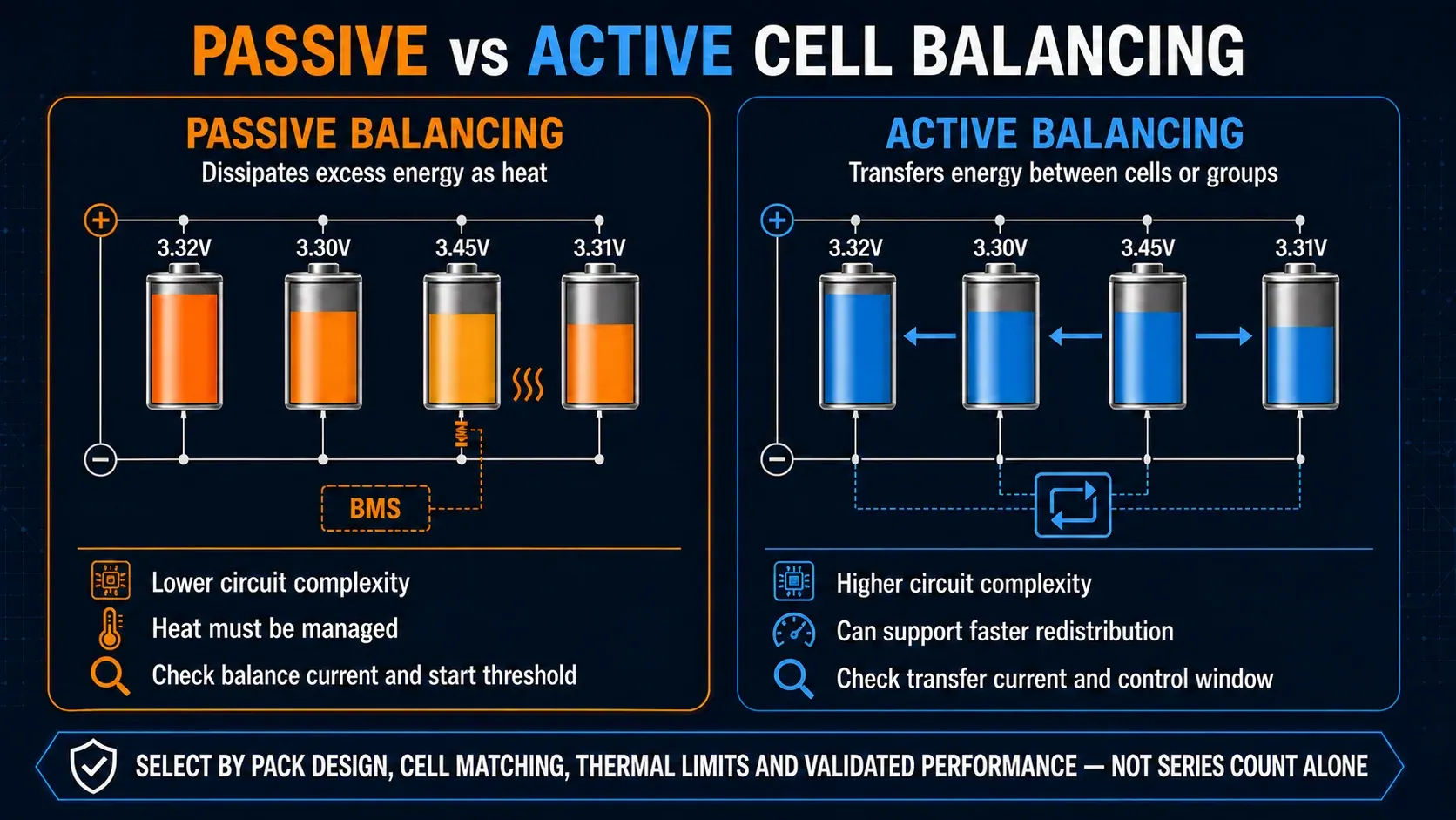
Avoid comparing passive and active balancing using a single universal “efficiency percentage.” The more useful B2B questions are: At what cell-voltage difference does balancing start? What is the balancing current? Is balancing active during charge, rest, or both? How much heat is generated?
Function 4: Temperature Management
The BMS should monitor enough temperature points to protect the cells and power components. Depending on the battery design, it may also command fans, liquid cooling, heaters, relays, or the PCS to reduce current.
For cold-weather installations, confirm whether low-temperature charging is blocked or whether a battery heater is integrated. For hot climates, evaluate enclosure temperature, cell spacing, cooling design, derating logic, and alarm history—not only the maximum cell temperature printed on a datasheet.
Function 5: State of Charge (SoC) Estimation
SoC is the battery's estimated remaining charge. BMS firmware may use coulomb counting, open-circuit-voltage correction, model-based estimation, or a combination of methods.
LiFePO4 batteries have a relatively flat voltage curve through much of their usable SoC range, which makes voltage-only estimation weak during normal operation. Accurate current measurement, calibration and periodic correction therefore matter.
For commissioning and troubleshooting, check whether the system provides an SoC calibration or full-charge synchronization procedure.
Function 6: State of Health (SoH) and Diagnostic Tracking
SoH is an estimate of battery degradation relative to its initial condition. Depending on the BMS, it may consider measured capacity, internal resistance, cycle count, temperature history, charge throughput, and fault events.
For B2B fleets, raw diagnostic data can be more useful than a single SoH percentage. Ask whether the platform records:
- minimum and maximum cell voltage
- cell-voltage delta
- maximum temperature
- charge/discharge current history
- cycle or energy-throughput count
- protection events
- communication failures
- firmware version
Function 7: Fault Handling and Safe Shutdown
A commercial BMS should detect faults, communicate operating limits, and move the battery into a safe state when required. Larger systems may also include insulation monitoring, contactor diagnostics, pre-charge monitoring, emergency-stop inputs, and master-slave coordination.
The procurement question is not simply “does it have protection?” Ask for the fault matrix: condition, warning threshold, trip threshold, delay time, action, recovery condition, and whether the event is logged.
What Safety Standards and Compliance Documents Should B2B Buyers Verify?
A common SEO mistake is to describe UL 1973, IEC 62619 and UN38.3 as if they were three universal “BMS certifications.” They are more accurately treated as battery or battery-system standards and transport test requirements in which BMS functions may be part of the overall safety evaluation.
A standalone BMS board does not automatically make the complete battery compliant. Buyers should verify the certification or test documentation for the actual battery model, module, rack, or energy storage system being purchased.
Key Standards and Documents
| Standard / Document | What It Applies To | Why It Matters for Solar Battery Procurement |
|---|---|---|
| UL 1973 | Batteries/modules/systems for stationary and motive auxiliary power applications | Important battery safety standard in North American stationary storage projects |
| UL 9540 | Complete energy storage systems and equipment | System-level certification used in North America; includes interaction of battery, controls and power conversion equipment |
| UL 9540A | Test method for thermal runaway fire propagation | Used to evaluate fire/thermal runaway behavior; not the same as UL 9540 system certification |
| IEC 62619:2022 | Secondary lithium cells and batteries for industrial applications | Covers safety requirements and tests for industrial lithium cells and batteries, including stationary applications |
| IEC 63056 | Secondary lithium cells and batteries used in electrical energy storage systems | Adds requirements specific to electrical energy storage applications, including PV and stationary storage |
| UN 38.3 | Lithium cell and battery transport testing | Required transport test framework for lithium cells and batteries; buyers should obtain the applicable test summary |
| CE / RoHS | EU regulatory conformity and restricted substances, where applicable | Market-access/documentation requirements, but not substitutes for battery safety testing |
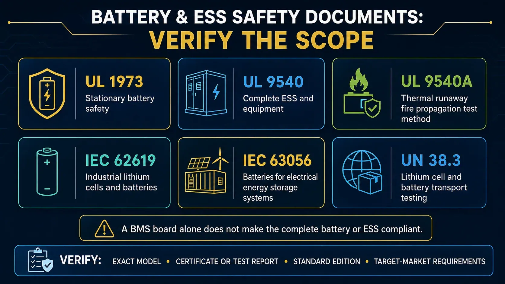
Important: “TÜV” is a testing/certification organization name, not a single battery safety standard. A supplier saying “TÜV certified” should identify the exact standard, product model, certificate number and issuing body.
Compliance Checklist for B2B Buyers
Before approving a battery order, request the documents relevant to the target market and shipment:
- Exact battery model and electrical specification
- Applicable safety certificate and/or test report for that model
- UN 38.3 test summary for the shipped lithium battery model
- MSDS/SDS and transport documents required by the forwarder or carrier
- Inverter/PCS compatibility documentation or test record where closed-loop communication is required
- Firmware and protocol version information
- Installation and commissioning manual
- Warranty terms and operating-condition exclusions
- Production/QC records available for the order
- Any local grid, electrical, fire, building or import documents required in the destination market
Compliance is market-specific. For a North American ESS, UL 9540 system requirements may be relevant in addition to UL 1973 battery certification. For other markets, IEC standards and local regulations may be more important.
How to Choose the Right BMS for a 48V or 51.2V Solar Battery
BMS selection starts with battery chemistry, series cell count, operating voltage, required current, inverter/PCS interface, thermal design, and compliance needs.
Why “48V LiFePO4” Usually Means a 51.2V 16S Battery
A LiFePO4 cell is commonly specified around 3.2V nominal. Sixteen cells in series produce:
16 × 3.2V = 51.2V nominal
This is commonly sold in the “48V-class” solar battery market. A 16S LiFePO4 BMS must therefore monitor 16 series cell groups.
The theoretical upper cell protection point is not the same thing as the recommended everyday charging voltage. If a cell's absolute overvoltage protection threshold is near 3.65V, multiplying 16 × 3.65V gives 58.4V, but the normal charge setpoint should follow the battery manufacturer's specification and communication limits rather than repeatedly charging to the BMS trip point.
Current Rating: Start From Power Demand
A useful first calculation is:
DC current ≈ inverter power ÷ battery voltage
For example, a 10kW inverter drawing from a 51.2V battery can require roughly:
10,000W ÷ 51.2V ≈ 195A
Actual current is affected by inverter efficiency, battery voltage under load, surge power, parallel battery sharing, cable losses and inverter limits. Therefore, the selected battery and BMS continuous-discharge rating must be safely above the expected operating current under the manufacturer's design rules.
If two batteries operate in parallel, do not automatically assume perfect 50/50 current sharing. Cable length, resistance, connection layout, battery SoC, internal resistance and BMS limits can affect current distribution.
BMS Selection Checklist
| Item | What to Verify | Procurement Risk if Ignored |
|---|---|---|
| Battery chemistry | LiFePO4, NMC or other chemistry | Wrong voltage/protection behavior |
| Series cell count | 16S, higher-voltage module structure, etc. | Incorrect cell monitoring |
| Continuous current | Charge and discharge separately | Power bottleneck or nuisance trips |
| Peak current | Magnitude and duration | Inverter surge may trigger protection |
| Cell-voltage limits | Alarm, cutoff and recovery values | Reduced life or repeated shutdowns |
| Temperature limits | Charge/discharge limits and sensor count | Unsafe operation or unnecessary derating |
| Balancing | Type, balance current, start condition | Long-term imbalance and usable-capacity loss |
| CAN/RS485 protocol | Exact protocol and firmware version | Inverter communication failure |
| Parallel/rack support | Addressing, master/slave rules, max modules | Expansion problems |
| Event logging | Fault code and historical data access | Difficult warranty diagnosis |
| Firmware update | Local/OTA process and version control | Long-term compatibility issues |
| Documentation | Test reports, manuals, transport files | Permit, shipping or project delay |
BMS Cost: What Actually Drives the Price?
There is no single reliable market percentage that a BMS should represent in every solar battery pack. Cost changes sharply with current rating, cell count, architecture, contactors, sensing hardware, balancing method, communication interfaces, functional safety design, enclosure, gateway, software, certification scope and production volume.
At the low end, basic protection boards can cost only tens of dollars. Smart low-voltage BMS assemblies with CAN/RS485 communication, higher current capability and monitoring can cost substantially more. Rack-level and high-voltage master-slave BMS systems can move into a completely different cost class.
For B2B procurement, a fixed “BMS price” is less useful than a feature-to-cost breakdown.
Main BMS Cost Drivers
| Cost Driver | Why It Changes Price |
|---|---|
| Series cell count | More monitored channels and isolation requirements |
| Continuous current | Larger MOSFETs, busbars, shunts, contactors and thermal design |
| Active balancing | Additional power electronics and control complexity |
| Redundancy | Extra sensing, control and shutdown paths |
| CAN/RS485/Ethernet | More interfaces, isolation and firmware development |
| Master-slave architecture | Multiple boards, rack controllers and communication links |
| Cloud monitoring | Gateway hardware, servers, software platform and support |
| Custom protocol | Firmware development and compatibility validation |
| Compliance testing | Engineering, test samples, laboratory work and documentation |
| Production volume | NRE and tooling are spread over more units at higher volume |
What to Ask for in a BMS Quotation
Instead of comparing only unit price, request:
- hardware part number and revision
- firmware version
- continuous/peak current
- balancing specification
- supported protocols
- included cables and harnesses
- software/cloud fees, if any
- engineering or NRE charges
- sample cost
- production MOQ
- test and validation scope
- warranty and failure-analysis process
This produces a much more useful B2B comparison than an online retail-board price.
OEM/ODM BMS Customization for Solar Battery Programs
OEM/ODM customization is useful when a standard battery BMS does not match the target inverter protocol, enclosure, connector layout, monitoring requirement, parallel configuration, branding program, or target-market documentation.
However, there is no universal MOQ or lead time for BMS customization. Those numbers depend on whether the change is only a parameter configuration, a protocol firmware change, a harness modification, a PCB revision, or a completely new battery platform.
Common Customization Levels
| Customization Type | Typical Work | What the Buyer Should Approve |
|---|---|---|
| Parameter configuration | Voltage/current/temperature limits | Parameter sheet and firmware version |
| Protocol configuration | CAN/RS485 message mapping | Inverter test result and protocol version |
| Harness/connector change | Pinout, cable length, terminal layout | Drawing, pin map and sample |
| Monitoring customization | App, gateway, API, branding | Data fields, user roles, cybersecurity and support scope |
| PCB/hardware revision | New board dimensions or power stage | Engineering validation and environmental testing |
| Full battery integration | BMS + cells + enclosure + inverter protocol | Complete DV/PV test plan and final product documentation |
Recommended OEM Procurement Workflow
- Define the battery platform — chemistry, nominal voltage, capacity, series/parallel architecture and current requirement.
- Define the inverter interface — exact inverter model, firmware, CAN/RS485 pinout and expected protocol.
- Define protection limits — cell voltage, pack voltage, current, temperature and recovery logic.
- Approve samples — verify electrical behavior, balancing, communication and fault handling.
- Run integration testing — charge/discharge test, inverter communication, parallel operation and abnormal-condition testing.
- Freeze hardware and firmware revisions — prevent production batches from shipping with unapproved changes.
- Approve production QC and documents — confirm inspection points, firmware traceability, labels, test reports and transport files.
For OEM battery programs, GINZA currently asks buyers to provide BMS, CAN/RS485, inverter-compatibility and target-market requirements before final confirmation. See the OEM solar battery supply page.
How a Solar Battery BMS Integrates With an Inverter or PCS
BMS-inverter integration is a closed-loop control relationship. The BMS measures the battery and sends information such as SoC, battery voltage, alarms, maximum charge current and maximum discharge current. The inverter or PCS uses that information to control charging and discharging.
Why CAN/RS485 Is Not Enough
In a commercial system, define what happens when the supervisory dispatch request exceeds a reported battery limit. The BESS controls responsibility guide shows how to assign the command, limit, measured result and fallback to the appropriate owners.
Two devices can both have a CAN port and still be incompatible. The same is true for RS485.
The following items must match:
| Integration Item | What to Confirm |
|---|---|
| Physical interface | CAN, RS485, Ethernet, etc. |
| Connector and pinout | CAN-H/CAN-L, RS485 A/B, ground, reserved pins |
| Baud rate | Must match both devices |
| Termination | CAN termination and RS485 topology must be correct |
| Application protocol | Message IDs/register map and data definitions |
| Battery profile | Inverter battery type/profile selection |
| Firmware version | Battery and inverter firmware compatibility |
| Current-limit messages | Charge/discharge limits interpreted correctly |
| Parallel addressing | Master battery and module addresses configured correctly |
Common Integration Problems
1. Protocol mismatch
The physical interface is correct, but the message format is different. A generic protocol converter is not always a safe or plug-and-play solution because the control semantics must also match.
2. Incorrect communication cable or pinout
RJ45 connectors are especially risky because different manufacturers may use different pins for CAN or RS485.
3. Wrong inverter battery profile
The inverter may be set to a different lithium battery protocol or to lead-acid/open-loop mode.
4. Firmware mismatch
A pairing that works on one inverter firmware version may behave differently after an update.
5. SoC disagreement
The inverter and battery may display different SoC values because of communication delay, BMS calibration, inverter display logic or incorrect commissioning.
6. Repeated BMS trips
If normal inverter charge/discharge settings repeatedly drive the battery into hard protection, operating limits and communication should be reviewed rather than treating the BMS trip as routine control.
7. Parallel battery addressing errors
Duplicate addresses, wrong master settings or unequal cable layouts can cause communication and current-sharing problems.
For a project quote, send the exact inverter model and communication requirements before ordering the battery. See the inverter compatibility guide for the information needed in a model-level review.
BMS Remote Monitoring and Fleet Management
Remote monitoring can help EPCs, installers and fleet operators identify abnormal cells, temperature trends, communication faults and repeated protection events before sending a technician to site.
The value is not a guaranteed percentage reduction in maintenance visits. It depends on data quality, alarm design, remote-access capability, the installer's troubleshooting process and whether the BMS exposes useful cell-level information.
Monitoring Feature Tiers
| Capability | Local Smart BMS | Project Monitoring | Fleet / Enterprise Monitoring |
|---|---|---|---|
| SoC and pack voltage | Yes | Yes | Yes |
| Individual cell voltages | Usually | Yes | Yes |
| Temperature data | Usually | Yes | Yes |
| Alarm/event history | Basic | Detailed | Detailed + cross-site search |
| Multi-battery view | Limited | Site-level | Multi-site |
| Remote firmware management | Sometimes | Optional | Often required |
| API integration | Rare | Optional | REST/MQTT/Modbus TCP depending on platform |
| User permissions | Basic | Multi-user | Role-based access |
| Data export | App-dependent | CSV/report | API + scheduled reporting |
Data That Matters Most for B2B O&M
A useful monitoring platform should expose more than SoC. For troubleshooting, prioritize:
- highest and lowest cell voltage
- cell-voltage delta
- highest and lowest temperature
- charge/discharge current limit
- active alarms and historical faults
- contactor or MOSFET state
- cycle/throughput data
- communication status
- battery/rack serial number
- firmware version
For cloud-connected BMS platforms, cybersecurity should also be part of procurement. Ask about account permissions, password policy, OTA authorization, API keys, encrypted transport, audit logs, server location requirements, and what happens if the cloud service is discontinued.
How GINZA Solar Supports BMS-Integrated Battery Procurement
GINZA Solar's public product range is centered on LiFePO4 solar batteries and energy storage systems with integrated BMS functions, rather than a separate catalog of standalone BMS boards. That distinction matters because most EPC and wholesale buyers ultimately need a complete battery that has been tested, documented and matched to the project—not only a BMS PCB.
GINZA's current 51.2V battery range includes 110Ah, 220Ah and 330Ah LiFePO4 models for installer, wholesale, EPC and OEM procurement. Public product information shows CAN/RS485 communication on relevant models, while the 51.2V 330Ah Gen5 product page also lists RS232. Compatibility should still be reviewed by exact inverter model and project conditions before supply.
For B2B inquiries, buyers should send:
- battery capacity or target kWh
- inverter brand and exact model
- required communication mode
- expected battery quantity
- parallel or rack configuration
- destination country and port
- required certificates and transport documents
- OEM logo, enclosure, label or packing needs
You can compare the current battery range on the solar battery procurement page or review the GINZA 51.2V 330Ah Gen5 LiFePO4 battery.
For larger projects, the commercial energy storage system guide explains how the BMS fits alongside the battery pack, PCS/inverter, EMS and safety system.
B2B Procurement Recommendation
Do not approve a solar battery only because the datasheet says “smart BMS.” Before placing a project or wholesale order, confirm the exact BMS current limits, protection logic, balancing behavior, CAN/RS485 protocol, inverter test status, firmware version, parallel configuration, monitoring access and documentation for the target market.
If you are preparing a multi-product RFQ, use the solar project BOM checklist and include the battery, inverter model, project capacity, destination port and required documents from the beginning.
FAQ: Solar Battery BMS
What is a solar battery BMS?
A solar battery BMS is the electronic management system inside or alongside a rechargeable battery pack. It monitors cell voltages, current and temperature, applies protection limits, manages balancing, estimates SoC and communicates battery operating limits to an inverter, PCS or EMS.
Does a LiFePO4 solar battery need a BMS?
Yes. A multi-cell LiFePO4 battery needs a properly designed battery management and protection system to monitor individual cells and prevent operation outside safe voltage, current and temperature limits. The BMS must match the cell count, current requirement and battery design.
What BMS is used for a 48V LiFePO4 solar battery?
Many “48V-class” LiFePO4 batteries use 16 cells in series, giving a nominal voltage of 51.2V. These packs require a BMS designed for 16S LiFePO4. The current rating and communication features must then be selected for the inverter power, battery design and project requirements.
Is 58.4V the correct charging voltage for every 51.2V LiFePO4 battery?
No. 58.4V corresponds to 16 × 3.65V, but an individual cell's upper protection threshold should not automatically be treated as the everyday charging setpoint. Use the battery manufacturer's specified charge voltage and BMS/inverter communication limits.
What is the difference between CAN and RS485 for a solar battery BMS?
CAN and RS485 are communication technologies commonly used between batteries, inverters, PCS units and monitoring equipment. Neither one guarantees compatibility by itself. The connector, pinout, baud rate, application protocol, firmware and message definitions must also match.
What is the difference between passive and active BMS balancing?
Passive balancing removes excess energy from higher-voltage cells as heat. Active balancing transfers energy between cells or cell groups. Active balancing can support higher balancing currents, but it also adds complexity and cost. Buyers should compare actual balancing current and control strategy rather than relying on a generic efficiency percentage.
What certifications should I ask for when buying a solar battery with BMS?
Ask for standards and test documents that apply to the complete battery or energy storage system in your target market. Depending on the project, this may include UL 1973, UL 9540, IEC 62619, IEC 63056 and UN 38.3 transport documentation. Do not assume these are standalone BMS certifications.
How do I know whether a battery BMS is compatible with my inverter?
Provide the exact inverter brand, model, firmware, battery voltage and expected communication mode. Compatibility requires more than matching CAN or RS485 ports; the application protocol, pinout, message definitions and current-limit logic must also match.
How much does a solar battery BMS cost?
BMS pricing varies widely. Basic protection boards can be inexpensive, while smart high-current BMS assemblies, active-balancing systems, master-slave rack BMS, gateways and cloud platforms cost much more. For B2B buying, compare the complete specification and engineering scope rather than a single online board price.
What BMS data should an installer record during commissioning?
Record battery voltage, SoC, highest and lowest cell voltage, cell delta, temperatures, charge/discharge current limits, active alarms, communication status, battery addresses, inverter profile and firmware versions. Saving screenshots and fault logs makes future troubleshooting much easier.
Technical References for Procurement Teams
For compliance and engineering review, verify requirements against the latest official documentation from the relevant standards body and equipment manufacturer. Useful references include:
- UL Solutions — energy storage system testing and certification
- IEC 62619:2022 — safety requirements for industrial lithium cells and batteries
- IEC 63056 — safety requirements for batteries used in electrical energy storage systems
- UNECE Manual of Tests and Criteria, Section 38.3 — lithium battery transport testing and test-summary requirements
- Battery and inverter manufacturer manuals — protocol, firmware, charge/discharge limits and commissioning instructions